QUICK NAVIGATOR
PRODUCTS
TECHNOLOGIES
DEVELOPMENT TOOLS
SmartDie™ Products
*Pentium® Processors & PCIset Components
*Intel486™ Microprocessors
*Flash Memory Components
[INTEL NAVIGATION HEADER]

SmartDie™ Products: Quality and Reliability

Die Products Qualification Methodology

Overview
Intel's SmartDie™ Products undergo product qualifications to ensure the quality and reliability performance of the die and to drive continuous improvement of the product and process. The qualification methodology validates the performance of a SmartDie product and demonstrates equivalence of a SmartDie product and its commercial packaged product counterpart.

Qualification Levels
Product qualifications consist of four major qualification levels designed to meet Intel's and customers' product introduction and production ramp needs. These levels are:

Levels attained during a product qualification are based upon meeting a set of requirements for each level. Level IV is achieved first, Level III next, etc. Each decreasing level demonstrates an increasing level of confidence in the quality and reliability of the product. A product shipment limit is associated with each level and determined by a Product Development Team (PDT). The different levels are achieved by meeting corporate defined quality and reliability goals. See Attachment 1 at the end of this section for the design, development, and SmartDie qualification flow.

Risk Assessment
Risk Assessment is a formal procedure that applies engineering knowledge and judgment to assess the expected performance and risks of adding a product to the SmartDie product line. The assessment identifies expected high, medium, and low risk areas for the product within the SmartDie process envelope. The process envelope is a defined set of characteristics based on the product's design and characteristics, wafer fabrication process, and manufacturing flow. The purpose of assessing how well a product fits into a process envelope is to understand if the product will be affected by known or unknown failure mechanisms. Risk levels are assigned to different aspects of a product's characteristics. A high level of risk is associated with little or no knowledge of how the product will perform to Level II requirements or some aspect of the product being significantly different than that of the process envelope. Medium risk is associated with an average likelihood that Level II requirements will be met. Low risk is associated with a product that has characteristics the same or similar to the process envelope and there is low probability that it will be not meet Level II requirements.

SmartDie are follow-on products to commercial packaged products. SmartDie products cannot achieve a higher qualification level than the packaged commercial product, and the commercial packaged version of a SmartDie product must be qualified to at least Level III before it can be qualified as a SmartDie. The processes and packages of the commercial product must also be Intel certified. All of these requirements are designed to ensure the likelihood of a successful SmartDie product qualification.

Pre-Qualification Activities
Various pre-qual activities are performed prior to initiating a SmartDie qualification. One is reviewing the reliability data of the commercial product and process to determine if there are existing issues that need to be considered in a SmartDie qualification. SmartDie product qualifications may use relevant commercial qual data for data sharing or referencing. The technology baseline should demonstrate that a SmartDie product will meet Level III requirements. If this is not the case, then Level IV status cannot be attained without the general manager's and Q&R manager's approvals. The SmartDie PDT is responsible for reviewing the product and process health.

If commercial data is not available or applicable to a SmartDie product, a pre-qualification engineering evaluation is required to promote proactive anticipation of problems and their resolution before a qualification begins. By identifying specific concerns that may impact a qualification and ship release schedule, strategies can be implemented to lower the risks. Pre-qual exercises could include engineering evaluations using extended stressing, step stressing to failure, or characterization oriented testing and the use of BART (see below).

Baseline Analysis and Reporting Tool (BART)
BART, Baseline Analysis and Reporting Tool, is a statistics based tool designed and used by Intel for reliability studies and calculations. Intel engineers use BART to calculate DPM (Defects Per Million) and FIT rates (Failures in Time) predictions for a particular process/product at various burn-in times (2 hours, 4 hours, 12 hours, etc.).

BART is most often used during an Intel product qualification to assess risks associated with the introduction of a new product or higher qualification of an existing product. BART utilizes statistics, device/process data, and/or raw burn-in yield data to predict the quality and reliability (DPM and FIT rates) of a device and to establish risk (high, medium, low). This information would be used to assist in the definition of qualification requirements for a new product, or qualification of an existing product on a new/different process. BART can also be used to evaluate the impact of a reduction in burn-in time, a die shrink, or wafer fabrication process/ISO (defect density) change.

Reliability Stresses

The following is an overview of typical reliability tests and stresses that are performed to qualify an Intel product.

Manufacturing Reliability
DLBI/T SmartDie qualifications use a Quality Validation (QV) check to verify the integrity of the manufacturing process and to demonstrate that the test program and hardware function correctly. QV testing of DLBI/T (generally microprocessor products and chip sets) involve re-testing devices at hot, cold, and room temperatures that have completed the full manufacturing flow. It measures outgoing electrical DPM and verifies test program guard bands, test repeatability, temperature range of testing, and any equipment setup issues. QV is typically the first test in a qualification. All qual units must pass QV before the rest of a qualification can proceed. Corrective action is required for any failures.

A Product Quality Validation (PQV) is used to determine manufacturing reliability on SmartSort Products (generally Flash products). A PQV consists of a risk assessment of the die processed through the SmartSort flow, and a yield and test bin-out comparison of SmartSort die to the same die in a package.

SmartSort products are continuously monitored by the PDT/QRE until the product achieves Level 3 qualification. Level 3 qualification of SmartSort products occur when room and/or hot temperature electrical testing are the only required test screens for the die in a package. In other words, when burn-in and cold temperature testing are not longer required to meet the quality and reliability goals for Level 3 and Level 2 qualification.

SmartSort die products on new designs or designs that are in the development phase often begin shipping to customers in quantity before the elimination of burn-in and cold temperature testing on the packaged product in order to meet the customer's sample and early production requirements. (The SmartSort flow does not include cold temperature testing and burn-in.) As a product progresses through the product maturity lifecycle, cold temperature testing and burn-in are eliminated on the packaged product. After these screens have been eliminated on packaged product, SmartSort products can achieve Level 3 or Level 2 qualification, and SmartSort products shipped to customers will be equivalent to the same die in a package.

SmartDie products use the same design and wafer fabrication process as packaged products. Therefore packaged device data for ESD and Latchup is referenced for SmartDie products (data sharing). Also, the SmartDie manufacturing test flow has been certified to Intel's stringent ESD control requirements. Customers must exercise precautions when handling SmartDie to minimize the risk of ESD/Latchup.

Moisture Reliability
Intel has traditionally packaged semiconductor products with Ceramic Pin Grid Array Packages, Tape Carrier Pack Packages, plastic encapsulant, etc. for physical and environmental protection, and ease of interfacing with a printed circuit board. An important feature of the package is to prevent/resist moisture contamination of the die. Intel performs moisture reliability stress testing during qualification of packaged products.

With the advent of Intel's SmartDie program, products are marketed and sold as unpackaged die. Because the die is not protected by a package, stresses used to evaluate the moisture performance of the package are not applicable, and moisture reliability stress testing is not included in the SmartDie product qualification plan. The Product QRE does review moisture performance data that was generated during the commercial product/package qualification of the die in a plastic package. This risk assessment is done to determine if the die has any moisture sensitivities.

For information on moisture-related stresses performed on Intel packaged products, see Appendix A.

Operating Reliability
Operating reliability is primarily measured with Infant Mortality Evaluations (IME) and High Voltage Extended Life Tests (HVELT). These stresses are used to accelerate failure mechanisms in the random failure/wear-out portion of a product's life curve by subjecting devices to high temperatures and voltages. IME is used to predict the infant mortality failure rate (0-50 hours) while HVELT predicts the early life (0-1 year) and long term life (1-10 years) failure rates. The following are SmartDie DPM (Defects Per Million) and FIT (Failures In Time) rate requirements:

SmartDie operating reliability must be predictable to the process baseline. Product burn-in fallout must be consistent with the technology baseline and to use BART, a product must pass a predictability test. Yield equivalency is demonstrated by examining sort and class yields to that of a reference product, both in percent defective and in failure mode distribution, after scaling for die size. Data should exist to show that no product wear-out occurs (no wear-out failures for a duration equivalent to at least four years of operating life).

NOTE: IME and ELT predictions for Flash products are generated using BART. BART process baseline data is generated using packaged products. Yield comparisons between packaged products and die products are made to validate that the BART IME and ELT predictions for die products are valid.

Mechanical Reliability
Mechanical reliability stresses, such as temperature cycling and surface mount conditioning, are usually performed during a packaged product qualification to assess the mechanical integrity of the protective packaging. Because SmartDie are not packaged, mechanical reliability stresses are generally not required as part of a die product qualification. Mechanical stresses may be required for a new product as an extension of the process certification envelop if an integral part of the process changed. An example of this would be an increase of pressure on the bond pads of the die from the burn-in/test die carrier used in the SmartDie process. Stress testing would be performed to assure the integrity of the silicon under the bond pads of the die.

Flash Memory Reliability
In addition to many of the previously mentioned tests and stresses, Flash products undergo the following stresses: Program/Erase Cycling and Data Retention Bake. The purpose of Program/Erase Cycling is to ensure that the memory array will operate for a specified number of program and erase operations, thus simulating actual device usage. The purpose of a data retention bake is to expose any possible charge loss mechanisms through high temperature acceleration. Since these stresses are package independent, data may be shared from commercial packaged product qualifications if available. If the commercial data does not exist, then flash reliability stresses are conducted using SmartDie.

Product Qualifications
After a device has been selected for qualification as a SmartDie product, the PDT (Product Development Team) reviews, revises as needed, and approves the qualification plan that is submitted to the PDT by the QRE (Quality and Reliability Engineer). The PDT consists of the QRE, Product Engineer (PE), Manufacturing Engineer (ME), and manufacturing support personnel. The qualification plan outlines the qualification target levels, risk assessments, required stresses, and sampling sizes. After approval by the participants, the qualification begins with the QV test. Only devices that have completed the full manufacturing flow are used in a qualification in order to assess customer representative material.

The qualification follows a pre-determined flow of reliability stresses as defined by the QRE. Any failures that occur are analyzed for root cause of failure and must be understood. Corrective action is required for any issue that arises during the qualification that may impact the product's health. At pre-determined test readout intervals, an assessment of the qual data is conducted before proceeding with the rest of the qualification.

Using BART, predictability and yield equivalency tests are conducted to determine if there is any evidence that the product is not performing as expected. Once all qualification stresses are completed and the data is analyzed and compared to the product qualification goals, the PDT determines if the product has achieved the target qualification level.

Postmortem Process
After a qualification has been completed, PDT members review the data and discuss significant observations listing major highlights/lowlights of the qualification procedure. The goal of this systematic review of the product development process is to identify elements and activities that worked well and those that can be improved. Owners are assigned to drive the process improvements.

A continuous improvement plan is developed to measure product performance against Intel requirements and baselines, and to customer goals and expectations. Product performance can be tracked by on-going health indicators such as yields, burn-in fallout, non-standard processing, test program changes, number of electrical test sockets, Statistical Bin Limits (SBL's), etc. Test program reviews and updates are conducted to ensure that appropriate test screens are in place. Any process or product changes are reviewed via the Change Control System to assess potential impacts on the customer and determine if customer notification is required.

A Product Reliability Summary Report is written by the QRE after qualification of the SmartDie product. Customers may request a copy of this report.

Summary
SmartDie products undergo a rigorous qualification procedure that begins with an extensive risk assessments and product/process review. This assessment includes a review of relevant commercial qualification data, evaluation of the product and process (wafer fabrication, manufacturing, test, etc.) health, and BART analysis. If necessary, an engineering pre-qual is conducted to validate or invalidate areas of concern and increase the likelihood of a successful qualification. After the initial assessments are completed, a qualification plan is developed and approved to qualify the device as a SmartDie product. The plan states the reliability requirements and goals, and the justification and reasoning behind the plan.

The SmartDie qualification is conducted with a detailed analysis of qual results in order to certify the well-being of the product's health. The goal is to demonstrate that performance is equivalent to or better than the packaged device. The assurance of the quality and reliability of the SmartDie does not end with the completion of a qualification. Performance continues to be monitored by ongoing health indicators and continuous improvement is driven throughout the product's lifetime.

Intel is committed to a SmartDie qualification methodology that does not compromise on performance or value and meets Intel's and the customer's strict quality and reliability requirements.

Manufacturing Quality and Reliability

Overview
Manufacturing Quality and Reliability (Q&R) has three main functions:

  • Process certification including certification of process changes.
  • Monitor the process.
  • Disposition of non-conforming material.

The SmartDie processes have been certified using Intel Corporation's documented process certification methodology. Once new processes are developed and certified as reliable and manufacturable, all subsequent changes are controlled, with emphasis on reliability and manufacturability. Major emphases of the Q&R group are on continuous improvement and representing the end user. Detailed information on Intel Corporation's process development systems, process certifications, and process control systems are located in chapters 3-5 in the Components Quality and Reliability Handbook (Order Number: 210997-005).

Process Certification
The certification of a new process is a joint activity between the technology development team and the Quality and Reliability (Q&R) organization. The end result is a process that exceeds both internal and external customer reliability and manufacturability performance needs. The Quality and Reliability organization's role in supporting manufacturing continues through-out the life of the process. The process certification plan is developed after a risk assessment is performed to identify the areas of concern within the process. Tests are then performed to validate that the process is not degrading the product. The focus areas of the process certification are based on the risk areas identified during the assessment. Listed below are analyses that were performed for the Die Level Burn-In and Test (DLBI/T) and SmartSort process certifications.

Die Backside Analysis: A visual inspection at 30X magnification to detect die backside damage caused by the die removal and pick-up procedure.

A Die Carrier Load/Unload (CLU) machine was developed to remove the die from the film frame and place it in the die carrier (temporary package) for burn-in and test. The sawed wafer is presented to the CLU on a film frame. The die is removed from the film frame with a needle or cluster of needles that pushes the die off of the adhesive film and up to a rubber collet. Vacuum gently holds the die on the collet. The microscope inspection of the backside of the die assured that the needle(s) did not damage the back of the die (chipped silicon, excessive scratches).

Bond Shear: Application of force to the ball bond to determine if the die carrier affects the long term ability of the ball bond to adhere to the bond pad.

Contacts (small conical shaped bumps) on the die carrier (temporary package) contact the bond pads forming an electrical connection between the die carrier and die for burn-in and test. Force is applied so the electrical contact is continuous. The contacts cause a minor disturbance to the bond pads. The devices used for process certification were wire bonded after completion of the manufacturing flow to simulate the processing that they would receive at the customer's factory and to assure that high manufacturing yields at wire bond could be attained. The bonds were then sheared to validate that the connection was reliable.

Cross Sections: Scanning Electron Microscopy of bond pads to determine if the die carrier contacts damage the structure underneath the bond pads.

Die were processed through the Die Level Burn-In/test Flow. They were then cross-sectioned through the die carrier contact impression on the bond pads to assure that the force applied by the die carrier contacts did not damage (fracture of cause microcracks) the silicon under the bond pads.

Quick Kill: Chemical etch process to detect passivation damage on the surface of the die.

Die were processed through the DLBI/T process. A portion of the die (from the inside edge of the bond pad to approximately 0.040 inches towards the center of the die) is contacted by a soft membrane in the die carrier. The etch process (Quick Kill) validates that the DLBI/T process does not excessively damage the nitride passivation. NOTE: Some microcracks in the nitride passivation are evident from the wafer fabrication process prior to the DLBI/T process.

Surface Analysis: X-Ray Dispersal Analysis for chemical contamination of the bond pads.

After DLBI/T processing, X-Ray Dispersal Analysis was done to validate that the bond pads on the die were free of any contamination caused by the DLBI/T process and die carrier contacts.

Accuracy of Placement in Gel-Paks: Die location was measured to validate 0.010" placement accuracy in the Gel-Pak.


This video clip illustrates
the CLU and DLBI processes.

CLU.AVI (2,281,208 bytes)

Download one of the following .exe files to allow the windows "Media Player" to play the video files. After expanding the file in an empty directory, run the setup.exe which will automatically configure Media Player for .avi files.

If you have Windows 3.1, download this file.
It will expand to 1,644,743 bytes

IVI16.EXE (1,594,721 bytes)
If you have Windows 95/NT, download this file.
It will expand to 1,515,143 bytes

IVI32.EXE (689,000 bytes)

Process Control
Process Controls, Process Monitors, Real-Time Inspections, and Quality Gates are added and deleted over time. They are eliminated once all critical parameters of the process are known and under control, and it can be demonstrated that the monitor/gate/etc. is no longer required. Additionally, monitors, gates, etc. can be added as needed if a shift of the process occurs and a monitor is required to maintain control and guarantee a high level of Quality and Reliability.

A Statistical Process Control called Statistical Bin Limits (SBL) is used during electrical testing of DLBI/T products. If electrical test and burn-in yields are not within the normal distribution for the product, the DLBI/T lot will fail the SBL and identify it as possible excursion material. An engineering/Q&R review of the material is done to disposition the lot. The lot may be dispositioned to continue as is, continue with an additional screen, or scrap.

Die Products Quality and Reliability Monitors
Quality and reliability monitors are most often embedded in the process flow. The critical parameters of the processes are identified and monitored to build quality and reliability into the products. On-line statistical process control systems have been implemented in many of Intel's manufacturing areas. SPC data can be viewed by engineering at any time to determine the health and predictability of the process. Automatic "Lock-outs" are being added to the on-line material processing system for excursion lots that exceed the Upper/Lower Control Limits (UCL/LCL)established for the process. The "lock-out" feature will not allow a production batch of material to be moved to the next step of the process until the lot has been dispositioned by engineering and Q&R.

SBL monitors (Statistical Bin Limits) are done at electrical test steps in the process flow including wafer sort. SBL's determine if the material falls within the normal distribution of the product or if it exceeds the UCL/LCL and is "different" (excursion material). SBL's monitor the yield and reject bins of the production lot.

Quality and reliability monitors for Die Products are interrelated with monitors for die in packaged products. An example of this is the End-Of-Line Monitor program (EOLM). Each wafer fabrication process is monitored once per month for early and extended life reliability. Wafer fabrication excursions identified through this monitor are also applicable to Die Products. The Die Products Quality and Reliability Engineers (QRE) will be notified if an excursion occurs. The Q&R organization determines the disposition of the suspect material.

A passivation integrity monitor has been added specifically for Die Products. Passivation integrity is determined by a chemical etch process that penetrates any cracks or punctures in the passivation. Currently this monitor is performed once per month per product per manufacturing line.

Customer Support
Intel's efforts towards total quality leadership and services for Die Products are driven by a central, uncompromising objective to make Intel and Die Products' customers successful. The same network of Sales Engineers, Applications Engineers, and Customer Quality Engineers in each geographical area that support customers of packaged products have been trained to support customers that use die products. Die Products customers will receive the same level of support that they receive on Intel's packaged products.

Change Notification
Die Products customers will receive notification of changes consistent with those they receive on packaged products. Since the die is the external package for Die Products Customers, notifications of changes to the die size (including die thickness), bond pad locations, size of the bond pads, and die passivation will be made. Customers will be notified 60 days prior to the change.

Functional Analysis/Correlation Requests (FA/CR)
Die Products customers can return die that is suspected of being defective through the same channels as packaged product. THE DIE MUST BE REMOVED FROM THE MODULE/SUBSTRATE BEFORE BEING RETURNED TO INTEL FOR ANALYSIS.

  • DIE LEVEL BURN-IN AND TEST DIE (uProcessors and Chip Sets)
  • Prior to retesting DLBI/T die, the bonds must be removed from the bond pads. Intel has developed a procedure to remove the gold ball bonds. Once the ball bonds have been removed the die is placed in the DLBI/T die carrier (temporary package) for functional testing. If emission microscopy or liquid crystal analysis is required, the returned die will be die attached and wirebonded in a standard semiconductor package.
  • SMARTSORT
  • SmartSort die (Flash products) must also be removed from the module or substrate before being returned to Intel for analysis. Intel has developed a procedure to retest SmartSort die on a wafer probe station, and is evaluating die carriers that can be used for functional testing of returned die. The gold removal process is also used with this test procedure.

Effective functional/failure analysis and corrective action is dependent upon historical records and information. TRACEABILITY TO PROCESSING RECORDS FOR INTEL DIE IS THROUGH INFORMATION ON THE LABEL OF THE GELPAK. THERE ARE NO MARKINGS ON THE DIE THAT PROVIDE TRACEABILITY TO INTEL'S LOT PROCESSING RECORDS. It is important that the users of die products retain the FPO number and ALT number with their module/substrate records. This is also important should Intel ever have to recall product. See Figure 1 below for an example of a Gel-Pak label.
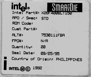

Figure 1 : Gel-Pak Label for SmartSort Products

Intel will provide available information regarding procedures for removal of die from the module or substrate as they are developed and refined. Please contact your local Field Sales Office or SMD Q&R for this information.

Appendix A -- Moisture Reliability
Listed below are descriptions of moisture reliability tests that Intel performs on packaged devices. These are provided as a reference for SmartDie customers that will be encapsulating/packaging SmartDie to provide physical and environmental protection and moisture resistance for the die. Intel makes every effort to minimize the impact of moisture during the processing and shipment of SmartDie products. The manufacturing environment minimizes the exposure of die to moisture through careful handling procedures. SmartDie are shipped in Gel-Paks and sealed in an anti-static moisture barrier bag (MBB) with desiccant. The seal date is printed on the label attached to the bag. The MBB with SmartDie do not need to be placed in a moisture controlled environment (Clean dry air or Nitrogen) as long as the bag remains sealed. The Gel-Pak should be stored within a temperature range of 0-70°C (maximum ratings).

It is recommended that the moisture barrier bag remain sealed until the die are to be used. If it is necessary to open the MBB prior to use of the die, the Gel-Pak with die should be placed in a nitrogen purged cabinet to prevent corrosion of the bond pads, or the bag should be resealed per MIL-B-81705, Paragraph 4.8.1 and MIL-B-81705, Paragraph 4.8.2. NOTE: Gel-Paks should only be opened in a clean room environment to prevent contamination of the die by foreign material.

The customer may consider performing moisture reliability evaluations of their encapsulated/packaged SmartDie components using similar reliability stresses to those referenced below. During certification of an Intel package or qualification of an Intel packaged product, the following moisture reliability stresses may be performed:

  • Surface Mount Preconditioning
  • THB (Temperature Humidity Bias) - 85 degrees C/85%RH
  • Steam (Autoclave)
  • Biased HAST (Highly Accelerated Steam Test)

Surface Mount Preconditioning

Surface Mount Preconditioning is used to simulate the processing conditions surface mounted devices encounter when soldered to the printed circuit board. The procedure simulates the environmental stresses (thermal and moisture) that a packaged device is subjected to during the process.

THB (85 degrees C/85%RH)

This test is a high temperature/high humidity stress used to evaluate the reliability of non-hermetic devices in humid environments. It accelerates the moisture absorption in a plastic package by increased humidity/temperature to induce the transport of ionic contamination. Devices are biased to the maximum voltage level within the operating range applied on alternate pins while maintaining minimum overall power dissipation in an 85°C ambient with 85% relative humidity environment. If contamination is present, it may combine with moisture to form an electrolyte. Typical failure mechanisms from this stress include electrolytic corrosion of metal and contamination induced threshold shifts due to moisture.

Steam (Autoclave)

The Steam stress accelerates moisture penetration through the plastic packaging material to the surface of the die. The objective of the test is to accelerate the problems found in very moist environments. Failure mechanisms typically seen from this stress include corrosion, passivation defects, leakage, and contamination. The test chamber is maintained at a temperature of 121°C and an absolute pressure of 2 atmospheres.

Biased HAST

The biased Highly Accelerated Steam Test (HAST) is similar to THB (85/85) except units are subjected to more stringent conditions. The HAST stress is run at 156°C with 85% relative humidity. The units are biased with the maximum voltage within the operating range applied on alternate pins while maintaining overall power dissipation. Typical failure mechanisms from this stress include electrolytic corrosion of metal and contamination induced threshold shifts due to moisture.

Additional related information is available in the following literature:

  • Intel Components Quality and Reliability Handbook
  • Intel Packaging Handbook
  • Board Solder Reflow Process Recommendations, Intel Faxback literature #8000
  • Guidelines for Handling Units in Desiccant Pack, Intel Faxback literature #8001


Legal Stuff © 1997 Intel Corporation
Free Web Hosting