Chapter 3
APPLICATION PROGRAMMING MODEL
This chapter describes the application programming environment as seen by compiler writers and assembly-language programmers. It also describes the architectural features which directly affect applications.
The Intel Architecture MMX™ technology introduces new packed data types, each 64 bits long. The data elements can be:
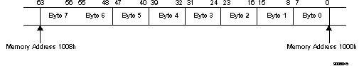
The low-order bits are the lower part of the data element and the high-order bits are the upper part of the data element. For example, a word contains 16 bits numbered 0 through 15, the byte containing bits 0-7 of the word is called the low byte, and the byte containing bits 8-15 is called the high byte.
Bytes in a multi-byte format have consecutive memory addresses. The ordering is always little endian. That is, the bytes with the lower addresses are less significant than the bytes with the higher addresses.
Values in IA MMX technology registers have the same format as a 64-bit quantity in memory. MMX technology registers have two data access modes: 64-bit access mode and 32-bit access mode.
The 64-bit access mode is used for 64-bit memory access, 64-bit transfer between MMX technology registers, all pack, logical and arithmetic instructions, and some unpack instructions.
The 32-bit access mode is used for 32-bit memory access, 32-bit transfer between integer registers and MMX technology registers, and some unpack instructions.
After each MMX technology instruction, the entire floating-point tag word is set to Valid (00s). The Empty MMX Technology State (EMMS) instruction sets the entire floating-point tag word to Empty (11s).
Section 4.3.2. describes the effects of floating-point and MMX technology instructions on the floating-point tag word. For details on floating-point tag word, refer to the Pentium® Processor Family Developer's Manual, Volume 3, Section 6.2.1.4.
Table 31 details the effect of a prefix on IA MMX Technology instructions.
|
| |
| Address size (67H) | Affects IA MMX technology instructions with a memory operand.
Ignored by IA MMX technology instructions without a memory operand. |
| Operand size (66H) | Ignored. |
| Segment override | Affects IA MMX technology instructions with a memory operand.
Ignored by IA MMX technology instructions without a memory operand. |
| Repeat | Ignored. |
| Lock (F0H) | Generates an invalid opcode exception. |
See the Pentium® Processor Family Developer's Manual, Volume 3, Section 3.4. for information related to prefixes.
Use the CPUID instruction to determine whether the processor supports the IA MMX technology instruction set (refer to the Pentium® Processor Family Developer's Manual, Volume 3, Chapter 25, for more detail on the CPUID instruction). When the IA MMX technology support is detected by the CPUID instruction, it is signaled by setting bit 23 (IA MMX technology bit) in the feature flags to 1. In general, two versions of the routine can be created: one with scalar instructions and one with MMX technology instructions. The application will call the appropriate routine depending on the results of the CPUID instruction. If MMX technology support is detected, then the MMX technology routine is called; if no support for the MMX technology exists, the application calls the scalar routine.
NOTE The CPUID instruction will continue to report the existence of the IA MMX technology if the CR0.EM bit is set (which signifies that the CPU is configured to generate exception Int 7 that can be used to emulate floating point instructions). In this case, executing an MMX technology instruction results in an invalid opcode exception.
Example 31 illustrates how to use the CPUID instruction. This example does not represent the entire CPUID sequence, but shows the portion used for IA MMX technology detection.X_ExampleOne
...			; identify existence of CPUID instruction
...
...			; identify Intel processor
....
mov	EAX, 1		; request for feature flags
CPUID			; 0Fh, 0A2h CPUID instruction
test	EDX, 00800000h	; Is IA MMX technology bit (Bit 23 of EDX) in feature flags set?
jnz	MMX_Technology_Found
When integrating the MMX technology routine into an application running under an existing operating system (OS), programmers need to take special precautions, similar to those when writing floating-point (FP) code.
When an MMX technology instruction executes, the floating-point tag word is marked valid (00s). Subsequent floating-point instructions that will be executed may produce unexpected results because the floating-point stack seems to contain valid data. The EMMS instruction marks the floating-point tag word as empty. Therefore, it is imperative to use the EMMS instruction at the end of every MMX technology routine.
The EMMS instruction must be used in each of the following cases:
The MMX technology enables direct access to all the MMX technology registers. This means that all existing interface conventions that apply to the use of other general registers such as EAX, EBX will also apply to the MMX technology register usage.
An efficient interface might pass parameters and return values via the pre-defined MMX technology registers, or a combination of memory locations (via the stack) and MMX technology registers. This interface would have to be written in assembly language since passing parameters through MMX technology registers is not currently supported by any existing C compilers. Do not use the EMMS instruction when the interface to the MMX technology code has been defined to retain values in the MMX technology register.
If a high-level language, such as C, is used, the data types could be defined as a 64-bit structure with packed data types.
When implementing usage of IA MMX technology instructions in high level languages other approaches can be taken, such as:
The MMX technology aliases the MMX technology registers on the floating-point registers. The main reason for this is to enable MMX technology to be fully compatible and transparent to existing software environments (operating systems and applications). This way operating systems will be able to include new applications and drivers that use the IA MMX technology.
An application can contain both floating-point and MMX technology code. However, the user is discouraged from causing frequent transitions between MMX technology and floating-point instructions by mixing MMX technology code and floating-point code.
3.3.4.1 RECOMMENDATIONS AND GUIDELINES
Do not mix MMX technology code and floating-point code at the instruction
level for the following reasons:
If the application contains floating-point and MMX technology instructions,
follow these guidelines:
FP_code:
		..
		..	(*leave the FP stackempty*)
MMX_code:
		..
		EMMS	(*mark the FP tag word asempty*)
FP_code 1:
		..
		..	(*leave the FP stack empty*)
An application needs to identify the nature of the multitasking operating system on which it runs. Each task retains its own state which must be saved when a task switch occurs. The processor state (context) consists of the integer registers and floating-point and MMX technology registers.
Operating systems can be classified into two types:
The behavior of the two operating system types in context switching is described in Section 4.1.1.
3.3.5.1 COOPERATIVE MULTITASKING OPERATING SYSTEM
Cooperative multitasking operating systems do not save the FP or MMX technology state when performing a context switch. Therefore, the application needs to save the relevant state before relinquishing direct or indirect control to the operating system. 3.3.5.2 PREEMPTIVE MULTITASKING OPERATING SYSTEM
Preemptive multitasking operating systems are responsible for
saving and restoring the FP and MMX technology state when performing a context
switch. Therefore, the application does not have to save or restore
the FP and MMX technology state.
MMX technology instructions generate the same type of memory-access exceptions as other Intel Architecture instructions. Some examples are: page fault, segment not present, and limit violations. Existing exception handlers can handle these types of exceptions. They do not have to be modified.
Unless there is a pending floating-point exception, MMX technology instructions do not generate numeric exceptions. Therefore, there is no need to modify existing exception handlers or add new ones.
If a floating-point exception is pending, the subsequent MMX technology instruction generates a numeric error exception (Int 16 and/or FERR#). The MMX technology instruction resumes execution upon return from the exception handler.
The IA MMX technology registers and their tags are mapped to
physical locations of the floating-point registers and their tags.
Register aliasing and mapping is described in more detail in Section 4.3.1.
Legal Stuff © 1997 Intel Corporation
