
| Disclaimer Information in this document is provided in connection with Intel products. No license, express or implied, by estoppel or otherwise, to any intellectual property rights is granted by this document. Except as provided in Intel's Terms and Conditions of Sale for such products, Intel assumes no liability whatsoever, and Intel disclaims any express or implied warranty, relating to sale and/or use of Intel products including liability or warranties relating to fitness for a particular purpose, merchantability, or infringement of any patent, copyright or other intellectual property right. Intel products are not intended for use in medical, life saving, or life sustaining applications. Intel may make changes to specifications and product descriptions at any time, without notice. Copyright © Intel Corporation (1996). Third-party brands and names are the property of their respective owners.
|
|
1.0. INTRODUCTION
3.0. MMX TECHNOLOGY BASEBAND ECHO CANCELER IMPLEMENTATION |
The media extension to the Intel Architecture (IA) instruction set includes single instruction, multi-data (SIMD) instructions. This application note presents an implementation of a common modem algorithm that takes advantage of these new instructions. Specifically, the baseband echo canceler function, ecmmx, demonstrates how the PMADDWD instruction can be used to perform complex FIR calculations efficiently and how use of the PUNPCKL and PUNPCKH instructions allow the adaptation of several filter coefficients at a time within a single loop.
The are two sources of echo in a modem. The near end (NE) echo signal is a combination of the reflection of the transmitted signal due to the impedance mismatches of the lines at the hybrid transformer on the modem board and the mismatches at the Public Switch Telephone Network(PSTN). The far end echo signal is a combination of the reflection of the transmitted signal due to impedance mismatches of the lines at the far end hybrid transformer on the receiving modem board and the mismatches at the far end of the PSTN (Figure 1). The near end echo has a much larger amplitude than the far end echo. The algorithm is the same for both the near end and far end echo cancelers. The difference is in the amount of delay in the buffer that holds the transmitted data used in the filter calculation, the delay is longer for the far end.
The baseband echo canceler is an adaptive filter that effectively cancels out the near and far end echos allowing the transmitted signal from the remote modem to arrive more cleanly at the receiver. The echo canceler can adapt because it knows the characteristics of its transmitted signal which appears in the echoes and can therefore subtract it out from the combined signal made up of the received signal and the echoes.
The MMX technology version of the baseband echo canceler consists of four parts:
Figure 2 shows the core operation performed by the code presented in this paper. The code loops three times to process each received baud that arrives at the modem because each baud is represented by three complex samples stored in the xI and xQ arrays. As a result, there are three pairs of complex filters that need to be calculated in the MMX technology version of the baseband echo canceler.
The data and received signal arrays, txdataI, txdataQ, xI, and xQ, are all 16-bit signed fixed point fractions. The coefficients, hI and hQ, are represented as 32-bit signed fixed point fractions but are stored as two 16-bit value arrays, hIH and hIL for the real coefficients and hQH and hQL for the imaginary coefficients. This is done because the higher 16 bits of the coefficients are used in the filter calculation while all 32 bits are used in the adaptation of the coefficients. These coefficients start out initialized as 0. The 'I' notation on the array names indicates the real part of the complex value and the ' Q' notation indicates the imaginary part. The hI arrays are stored in memory as [hIH0 hIH1 hIH2] and [hIL0 hIL1 hIL2] where each of the subscripts denotes one of the three complex filters while the hQ arrays are stored as [hQH0 hQH1 hQH2] and [hQL0 hQL1 hQL2]. Each filter is the same length which must be a multiple of 8 in this implementation.
The formula used to calculate the complex FIR output is as follows:
where txdata is the transmitted data and h are the filter coefficients
The formula for the calculation of the real output and imaginary output were derived as follows:
real filter output:
imaginary filter output:
By using the PMADDWD instruction the filter loop can be performed quite efficiently. In each loop iteration it is possible to calculate two of the multiply/add and subtract operations for the real filter output calculation and two multiply and add operations for the imaginary filter output calculations. Only the high order 16-bits of the coefficients are used in this calculation. The following figure shows how the filter is performed. Register MM0 is used as the accumulator for the real filter output while MM1 is used for the imaginary filter output.
There are a few initial conditions set before the complex FIR loop is entered. Register MM4 is preloaded with the first four values in the txdataI array and the accumulator registers are cleared. These instructions are done so that the loop of the FIR filter can be paired efficiently. As a result of this instruction reordering, after the loop is complete MM5 and MM6 must be subtracted from MM0 and added to MM1 respectively.
; Complex FIR Loop
FIRLoop:
	pmaddwd	mm4, [ecx+edi]		   	; Compute txdataI*hIH value
	psubd		mm0, mm5		; Accumulate real filter sum

	movq		mm5, [ebx+edi]		; Read in txdataQ values
	paddd		mm1, mm6		; Accumulate imag. filter sum

	pmaddwd	mm7, [edx+edi]		  	; Compute txdataI*hQH value
	movq		mm6, mm5		; Copy txdataQ value from mm5

	pmaddwd	mm5, [edx+edi]		    	; Compute txdataQ*hQH value
	paddd		mm0, mm4		; Accumulate real filter sum

	movq		mm4, [eax+edi+8]	Load next set of txdataI to be used

	pmaddwd	mm6, [ecx+edi]		      	; Compute txdataQ*hIH value
	paddd		mm1, mm7		; Accumulate imag. filter sum

	movq		mm7, mm4		; Copy txdataI value from mm4
	add		edi, 8			; Increase data pointer by 8 bytes

	sub		esi, 4			; Decrement counter value
	jg		FIRLoop			; If no more filter taps then done with
						; loop
;End of Loop for FIR

	psubd		mm0, mm5		; Final accumulate for real filter
	paddd		mm1, mm6		; Final accumulate for imag filter)
To get the final result of the real filter MM0 is then copied into MM2 and shifted right by 32 bits and added back to MM0. The imaginary result mm1 is copied to MM3 and shifted right by 32 bits and added back to MM1. These values are then scaled to 16-bit values so the new received signal can be calculated.
The values of the received data, both real and imaginary are then read into a register and the filtered echo signal is subtracted from them.
xInew = xIreceived yI where yI is the real filtered value
These new xI and xQ are stored back into memory and are also used as the error signal used to adapt the coefficients of the filters (see Figure 2).
The are two loops that take care of the filter coefficient adaptation. First, the real coefficients are adapted and then the imaginary coefficients are calculated in the second loop. This is done because the technique used did not leave enough MMX registers to accomplish both adaptations within one loop. The error signals were stored in the way they were(see figure 4) so that for every loop iteration four coefficients could be adapted at a time. The following equations were used for adaptation:
where m = adaptation step size (0.125 in this code), e = error signal (xInew and xQnew in this code), and d* = the conjugate of the transmitted data (txdata in this code).
Expanding out the above equation provides the individual equations used in the adaptation loops.
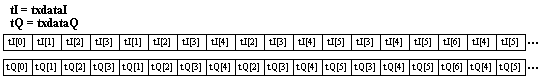
In the above equations notice that for the adaptation of the filter coefficients the error values, xInew and xQnew, must be multiplied by each data value, txdataI or txdataQ, associated with the coefficient being adapted. For example, to adapt the first coefficient hI[0](full 32-bit value) the error value xInew would be multiplied with txdataI[0] and value xQnew would be multiplied with txdataQ[0] and they would be added together. By storing the complex error signals interleaved with zeroes, multiple adaptation of coefficients can occur in the adaptation loops.
For example, by using real_diff1, the PMADDWD instruction, and the txdataI value and adding it to the result of using imag_diff1, the PMADDWD instruction, and the txdataQ value to the second and fourth coefficients could be adapted (see Figure 5). After the PADDD instruction is performed the data then only needs to be shifted by three bits to the right, which equates to a multiplication of m equal to 0.125, and it is ready to be added to the previous 32-bit coefficient for adaptation(see Figure 6). Similiarly, real_diff2 and imag_diff2 are used to calculate the adaptation for the first and third coefficient. The adaptation equation is described in further detail in the next section.
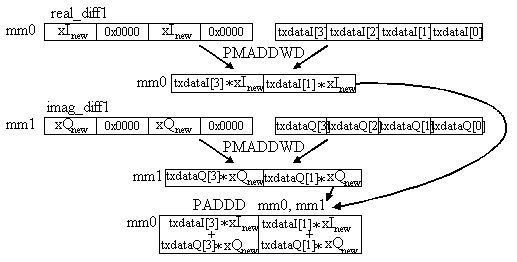
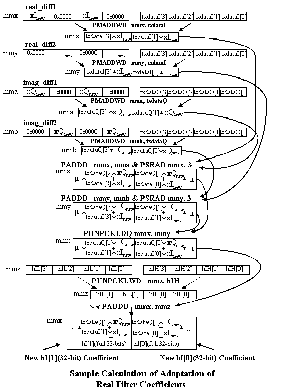
Figure 6 shows in more detail how the adaptation of the first two real coefficients is done. These same instructions are used in the adaptation loops to accomplish the adaption of the next six real coefficients. The same instructions are used in the adaptation of the imaginary coefficients.
Since the coefficients are 32-bits but are stored in an array of high 16-bit coefficients and an array of low 16-bit coefficients, unpacking and shifting operations must be used to manipulate the data properly to get the correct outcome of the equation for filter coefficient adaptation. The PUNPCKHWD, PUNPCKLWD, and PSRAD are used to accomplish the adaptation but since they all use the MM shifter unit they cannot be paired with each other. Each of the loops were unrolled once so that pairing could be improved. So now in each loop iteration eight coefficients are adapted. The value of m was chosen as a fixed value of 0.125 which is just a shift of three bits to the right. After the new coefficients are generated they must be unpacked into their high and low 16-bit values before they are stored back into memory.
It may be possible to reduce the number of cycles that the echo canceler code performs by making adjustments in how the data arrays are passed into the function to reduce the number of misaligned data accesses. For example, currently the transmit data, txdataI and txdataQ. are passed into the function as sequential arrays and the way the filters operate on them causes misaligned accesses three out four times because the pointer to these arrays is incremented by two bytes for every filter output calculation. Perhaps four copies of the data could be passed in for each the real and imaginary data, each copy being a shifted version of the original array, thus preventing misaligned accesses if the algorithm was thought out with the data in this structure. The overhead of making these multiple copies would be amortized by the fact that the same txdata is used many times as the FIR and adaptation loops execute.
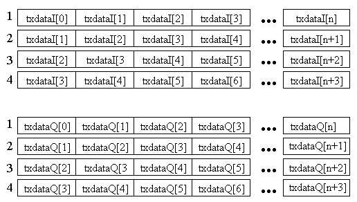
During the calculation of the first filter output, the arrays starting with the txdataI[0] and txdataQ[0] elements would be used. The next filter output would be calculated using the arrays starting with txdataI[1] and txdataQ[1], the next using txdataI[2] and txdataQ[2], and the next using txdataI[3] and txdataQ[3]. The next iteration the pointer to the array could be incremented by 8 bytes and the first arrays could be used for the next calculation.
An even better way, to avoid the problem of having to have eight pointers to the various arrays is to arrange two arrays as described in Figure 8. This way there are only two pointer values that have to be stored and the same amount of memory is used to store the arrays.
;*  Description
:
;*			This file is an example of one way to implement a baseband echo canceler
;*			in MMX technology and will serve as an instructional example.
;*
;*  Assumptions:
;*
;*			1. The number of coeffcients in the filters is a multiple of 8.
;*			2. The number of baud being processed is a multiple of four.
;*			3. The arrays passed into this routine are ordered in a specific way
;*			   described later.
;*

	title	 	EchoCancelerMMX
	.486P

.model		flat, c

; Local Variable Declarations
; 		1. Filt_Num 	- keeps track of which of the three filter is being
;		                performed
;		2. Baud_Count	- number of baud being processed in this block
;		3. Rx_real	- address where real received data is stored in memory
;		4. Rx_imag	- address where imaginary received data is stored in memory
;		5. dword_mask	- word mask used with MMX register
;		6. real_diff1	- used to store the real error signal in this format
;				  error | 0x0000 | error | 0x0000
;		7. real_diff2	- used to store the real error signal in this format
;				  0x0000 | error | 0x0000 | error
;		8. imag_diff1	- used to store the imaginary error signal in this format
;				  error | 0x0000 | error | 0x0000
;		9. imag_diff2	- used to store the imaginary error signal in this format
;				  0x0000 | error | 0x0000 | error

; In the comments for the code the dI array notation indicates the txdataI array
; while the dQ array notation indicates the txdataQ array that are passed in.
; First real set of coefficients start at hIH[0] and go to hIH[n-1] where n is the
; length of the filter and filter #2's coefficients start at hIH[n] and got to
; hIH[2n-1] and filter #3's coefficients start at hIH[2n] and got to hIH[3n-1].
; This is the way hQH array is set up and hIL array and hQL array.

.code

EchoCancelerMMX 	PROC C uses ebx ecx edx esi edi,
					txdataI:PTR WORD,
					txdataQ:PTR WORD,
					xI:PTR WORD,
					xQ:PTR WORD,
					hIH:PTR WORD,
					hQH:PTR WORD,
					hIL:PTR WORD,
					hQL:PTR WORD,
					h_Leng:DWORD,
					x_Leng:DWORD
	LOCAL	Filt_Num:DWORD
	LOCAL	Baud_Count:DWORD
	LOCAL	Rx_real:DWORD
	LOCAL	Rx_imag:DWORD
	LOCAL	dword_mask:DWORD
	LOCAL	real_diff1[2]:DWORD
	LOCAL	real_diff2[2]:DWORD
	LOCAL	imag_diff1[2]:DWORD
	LOCAL	imag_diff2[2]:DWORD

mov			Filt_Num, 0000H
mov			esi, xI

mov			dword_mask, 0FFFFH
mov			eax, txdataI

mov			ebx, txdataQ
mov			Rx_real, esi

mov			ecx, hIH
mov			esi, xQ

mov			edx, hQH
mov			Rx_imag, esi

mov			esi, x_Leng
mov			edi, 0				; edi = address incrementer for input data

mov			Baud_Count, esi
mov 			esi, h_Leng			; esi = filter length

; This section of code is where the complex FIR is calculated.  Before entering
; the loop mm4 is preloaded with first 4 real elements from data array so that
; better pairing can be accomplished.  The accumulators mm0 and mm1 are also
; initialized to 0.

FilterLoop:
	pxor		mm0, mm0
	pxor		mm1, mm1

	sub		ecx, edi			; adjust pointer to hIH
	sub		edx, edi			; adjust pointer to hQH

	mov 		esi, h_Leng			; esi = filter length
	pxor		mm6, mm6

    	movq		mm4, [eax+edi]			; mm4 = dI[3] | dI[2] | dI[1] | dI[0]
	pxor		mm5, mm5

	mov		ebx, txdataQ
	movq		mm7, mm4

	; Complex FIR Loop
	FIRLoop:
		pmaddwd	mm4, [ecx+edi]			; mm4 =
							; dI[3]*hIH[3] + dI[2]*hIH[2] |
							; dI[1]*hIH[1] + dI[0]*hIH[0]
		psubd		mm0, mm5		; mm0 -= mm5 (hQH * dQ)

		movq		mm5, [ebx+edi]		; mm5 =
							; dQ[3] | dQ[2] | dQ[1] | dQ[0]
		paddd		mm1, mm6		; mm1 += mm6 (hIH * dQ)

		pmaddwd	mm7, [edx+edi]			; mm7 =
							; dI[3]*hQH[3] + dI[2]*hQH[2] |
							; dI[1]*hQH[1] + dI[0]*hQH[0]
		movq		mm6, mm5		; mm6 =
							; dQ[3] | dQ[2] | dQ[1] | dQ[0]

		pmaddwd	mm5, [edx+edi]			; mm5 =
							; dQ[3]*hQH[3] + dQ[2]*hQH[2] |
							; dQ[1]*hQH[1] + dQ[0]*hQH[0]
		paddd		mm0, mm4		; mm0 += mm4 (hIH * dI)

		movq		mm4, [eax+edi+8]	; mm4 =
							; dI[3] | dI[2] | dI[1] | dI[0]

		pmaddwd	mm6, [ecx+edi]			; mm6 =
							; dQ[3]*hIH[3] + dQ[2]*hIH[2] |
							; dQ[1]*hIH[1] + dQ[0]*hIH[0]
		paddd		mm1, mm7		; mm1 += mm7 (hQH * dI)

		movq		mm7, mm4		; mm7 =
							; dI[3] | dI[2] | dI[1] | dI[0]
		add		edi, 8			; increase data pointer by 8 bytes

		sub		esi, 4			; decrement counter value
		jg		FIRLoop			; if >0 then do loop again
	;End of Loop for FIR

	psubd		mm0, mm5			; mm0 -= mm5 (hQH * dQ)
	paddd		mm1, mm6			; mm1 += mm6 (hIH * dQ)

; Here the final complex result of the filter is calculated by copying mm0,
; shifting the copied value 32-bits to the right and adding it back to mm0.
; The same thing is done for the imaginary result in mm1.

	; mm0 = yI = (hIH[3,2] * dI[3,2]) - (hQH[3,2] * dQ[3,2])
	; 		| (hIH[1,0] * dI[1,0]) - (hQH[1,0] * dQ[1,0])
	; mm1 = yQ = (hIH[3,2] * dQ[3,2]) + (hQH[3,2] * dI[3,2])
	;		 | (hIH[1,0] * dQ[1,0]) + (hQH[1,0] * dI[1,0])

	movq		mm2, mm0
	movq		mm3, mm1

	movdt		mm4, dword_mask
	psrlq		mm0, 32				; mm0 = 0x00000000
							; | (hIH[3,2]*dI[3,2])-(hQH[3,2]*dQ[3,2])

	psrlq		mm1, 32				; mm1 = 0x00000000
							; | (hIH[3,2]* Q[3,2])+(hQH[3,2]*dI[3,2])
	paddd		mm0, mm2			; mm0 = single real output of filter
							;     = xxxx | (hIH*dI)-(hQH*dQ)

	mov		eax, Rx_Real
	paddd		mm1, mm3			; mm1 = single imaginary output of filter
							;     = xxxx | (hIH*dQ)+(hQH*dI)

; This section of code reads in the complex received values and subtracts off the
; filtered value.  Then it stores the new received value back into memory and
; stores it back in variables real_diff1, real_diff2, imag_diff1, and imag_diff2
; to be used later in adaptation.

	mov		ebx, Rx_Imag
	psrld		mm0, 14			; adjust output value to lowest 16 bits of mm0
						; YI & introduce gain of 2
						; xxxx | xxxx | xxxx | YI

	movq		mm2, [eax]
	psrld		mm1, 14			; adjust output value to lowest 16 bits of mm1
						; YQ & introduce gain of 2
						; xxxx | xxxx | xxxx | YQ

	movq		mm3, [ebx]
	psubw		mm2, mm0

	psubw		mm3, mm1
	pand		mm2, mm4

	pand		mm3, mm4
	movq		mm7, mm2		; mm7 = 0x0000 | 0x0000 | 0x0000 | xI

	movq		mm6, mm2		; mm7 = 0x0000 | 0x0000 | 0x0000 | xI
	psllq		mm7, 32			; mm7 = 0x0000 | xI     | 0x0000 | 0x0000

	movdf		ecx, mm2
	por		mm6, mm7		; mm6 = 0x0000 | xI     | 0x0000 | xI

	mov		WORD PTR [eax], cx
	movq		mm7, mm6		; mm7 = 0x0000 | xI     | 0x0000 | xI

	add		eax, 2
	movq		mm4, mm3		; mm5 = 0x0000 | 0x0000 | 0x0000 | xQ
	mov		Rx_Real, eax
	movq		mm5, mm3		; mm5 = 0x0000 | 0x0000 | 0x0000 | xQ

  	movdf		edx, mm3
	psllq		mm6, 16			; mm6 = xI     | 0x0000 | xI     | 0x0000

	mov		WORD PTR[ebx], dx
	add		ebx, 2

	movq		real_diff1, mm6
	psllq		mm5, 32			; mm5 = 0x0000 | xQ     | 0x0000 | 0x0000

	movq		real_diff2, mm7
	por		mm4, mm5		; mm4 = 0x0000 | xQ     | 0x0000 | xQ

	mov		Rx_Imag, ebx
	movq		mm5, mm4		; mm5 = 0x0000 | xQ     | 0x0000 | xQ

	psllq		mm4, 16			; mm4 = xQ     | 0x0000 | xQ     | 0x0000
	mov		ecx, hIH

; Here the base address for the filter coefficients to be adapted is calculated.
; Since the coefficients are stored [hIH0 hIH1 hIH2] and [hIL0 hIL1 hIL2] the
; pointer to the coefficients needs to be adjusted if it is your first iteration
; and hIH0 hIL0 needs to be pointed to, or the second iteration where hIH1 hIL1( =
; (hIH0 hIL0) + 2 * length of filter) needs to be pointed to, or the third
; iteration where hIH2 hIL2( = (hIH0 hIL0) + 4 * length of filter) needs to be
; pointed to.

	mov		edx, hIL		; load edx with base address of low 16-bits
 	mov		ebx, Filt_Num		; of real filter coefficients

	mov		eax, h_Leng		; h_Leng = offset needed to point to correct
	mov		esi, h_Leng		; set of coefficients to be adapted

   	movq		imag_diff1, mm4		; store imag. error for adaptation

	movq		imag_diff2, mm5

	dec		ebx			; determine which filter is being done this
	jg		real_adapt2		; time through loop

	jl		real_adapt

	real_adapt1:
		shl 		eax, 1
		jmp		do_real_adapt

	real_adapt2:
		shl 		eax, 2
		jmp		do_real_adapt

	real_adapt:
		mov		eax, 0

	do_real_adapt:
	add			ecx, eax	; point to correct set of coefficients to
 	add			edx, eax	; adapt

	sub			edi, esi
	mov			eax, txdataI

	sub			edi, esi
	mov			ebx, txdataQ

	sub			ecx, edi
	sub			edx, edi

; This section of code performs the loop that calculates the real coefficient
; adaptation.
; real hnew = real hold + mu * (real error * real data + imag error * imag data)
; mu = 0.125 (shift right by 3 bits)
; real data = txdataI = dI in comments
; real error = xI
; imag data = txdataQ = dQ in comments
; imag error = xQ

	; Adaptation loop for real coefficients

	Adapt_Real:
		movq		mm7, real_diff2		; mm7 = 0x0000 | xI | 0x0000 | xI
		movq		mm0, mm6		; mm0 = xI     | 0x0000 | xI     | 0x0000

		pmaddwd	mm0, [eax+edi]			; mm0 =xI * dI[3] | xI * dI[1]
		movq		mm2, mm4		; mm2 = xQ     | 0x0000 | xQ     | 0x0000

		pmaddwd	mm2, [ebx+edi]			; mm2 =xQ * dQ[3] | xQ * dQ[1]
		movq		mm1, mm7		; mm1 = 0x0000 | xI     | 0x0000 | xI

		pmaddwd	mm1, [eax+edi]			; mm1 =xI * dI[2] | xI * dI[0]
		movq		mm3, mm5		; mm3 = 0x0000 | xQ     | 0x0000 | xQ

		pmaddwd	mm3, [ebx+edi]			; mm3 =xQ * dQ[2] | xQ * dQ[0]

		pmaddwd	mm6, [eax+edi+8]		; mm6 =xI * dI[7] | xI * dI[5]
		paddd 		mm0, mm2		; mm0 =xI*dI[3]+xQ*dQ[3] | xI*dI[1]+xQ*dQ[1]

		pmaddwd	mm4, [ebx+edi+8]		; mm4 =xQ * dQ[7] | xQ * dQ[5]
		psrad		mm0, 3			; multiply by mu(0.125)

		pmaddwd	mm7, [eax+edi+8]		; mm7 =xI * dI[6] | xI * dI[4]
		paddd		mm1, mm3		; mm1 = xI*dI[2]+xQ*dQ[2] | xI*dI[0]+xQ*dQ[0]

		pmaddwd	mm5, [ebx+edi+8]		; mm5 =xQ * dQ[6] | xQ * dQ[4]
		psrad		mm1, 3			; multiply by mu(0.125)

		movq		mm2, mm0		; mm2 =mu*(xI*dI[3]+xQ*dQ[3] | xI*dI[1]+xQ*dQ[1])
		movq		mm3, mm1		; mm3 = mu*(xI*dI[2]+xQ*dQ[2] |  xI*dI[0]+xQ*dQ[0])

		punpckldq	mm1, mm2		; mm1 = mu*(xI*dI[1]+xQ*dQ[1] | xI*dI[0]+xQ*dQ[0])
		paddd 		mm6, mm4		; mm6 =xI*dI[7]+xQ*dQ[7] | xI*dI[5]+xQ*dQ[5]

		punpckhdq	mm3, mm0		; mm3 = mu*(xI*dI[3]+xQ*dQ[3] | xI*dI[2]+xQ*dQ[2])
		paddd		mm7, mm5		; mm7 = xI*dI[6]+xQ*dQ[6] | xI*dI[4]+xQ*dQ[4]
		movq		mm0, [edx+edi]		; mm0 = hIL[3] | hIL[2] | hIL[1] | hIL[0]
		psrad		mm6, 3			; multiply by mu(0.125)

		movq		mm2, mm0		; mm2 = hIL[3] | hIL[2] | hIL[1] | hIL[0]
		psrad		mm7, 3			; multiply by mu(0.125)

		punpckhwd	mm0, [ecx+edi]		; mm0 = hIH[3] | hIL[3] | hIH[2] | hIL[2]
		movq		mm4, mm6		; mm4 =mu*(xI*dI[7]+xQ*dQ[7] | xI*dI[5]+xQ*dQ[5])

		punpcklwd	mm2, [ecx+edi]	 	; mm2 = hIH[1] | hIL[1] | hIH[0] | hIL[0]
		movq		mm5, mm7		; mm5 = mu*(xI*dI[6]+xQ*dQ[6] | xI*dI[4]+xQ*dQ[4])

		paddd		mm0, mm3		; mm0 = hnew[3,2] = hold[3,2] + mu*error*D
							;     = hIH[3] | hIL[3] | hIH[2] | hIL[2]
		punpckldq	mm7, mm4		; mm7 = mu*(xI*dI[5]+xQ*dQ[5] | xI*dI[4]+xQ*dQ[4])

		paddd		mm1, mm2		; mm1 = hnew[1,0] = hold[1,0] + mu*error*D
							;     = hIH[1] | hIL[1] | hIH[0] | hIL[0]
		punpckhdq	mm5, mm6		; mm5 = mu*(xI*dI[7]+xQ*dQ[7] | xI*dI[6]+xQ*dQ[6])

		movq		mm6, [edx+edi+8]	; mm6 = hIL[7] | hIL[6] | hIL[5] | hIL[4]
		movq		mm2, mm0		; mm2 = hnew[3,2] = hold[3,2] + mu*error*D
							;     = hIH[3] | hIL[3] | hIH[2] | hIL[2]

		movq		mm4, mm6		; mm4 = hIL[7] | hIL[6] | hIL[5] | hIL[4]
		psrlq		mm2, 32			; mm2 = 0x0000 | 0x0000 | hIH[3] | hIL[3]

		punpckhwd	mm6, [ecx+edi+8]	; mm6 = hIH[7] | hIL[7] | hIH[6] | hIL[6]
		movq		mm3, mm1		; mm3 = hnew[1,0] = hold[1,0] + mu*error*D
							;     = hIH[1] | hIL[1] | hIH[0] | hIL[0]

		punpcklwd	mm4, [ecx+edi+8]	; mm4 = hIH[5] | hIL[5] | hIH[4] | hIL[4]
		paddd		mm6, mm5		; mm6 = hnew[7,6] = hold[7,6] + mu*error*D
							;     = hIH[7] | hIL[7] | hIH[6] | hIL[6]

		psrlq		mm3, 32			; mm3 = 0x0000 | 0x0000 | hIH[1] | hIL[1]
		paddd		mm7, mm4		; mm7 = hnew[5,4] = hold[5,4] + mu*error*D
							;     = hIH[5] | hIL[5] | hIH[4] | hIL[4]

		punpckldq	mm2, mm0		; mm2 = hIH[2] | hIL[2] | hIH[3] | hIL[3]
		movq		mm4, mm6		; mm4 = hnew[7,6] = hold[7,6] + mu*error*D
							;     = hIH[7] | hIL[7] | hIH[6] | hIL[6]

		movq		mm5, mm7		; mm5 = hnew[5,4] = hold[5,4] + mu*error*D
		punpckldq	mm3, mm1		; mm3 = hIH[0] | hIL[0] | hIH[1] | hIL[1]

		punpcklwd	mm0, mm2		; mm0 = hIH[3] | hIH[2] | hIL[3] | hIL[2]

		punpcklwd	mm1, mm3		; mm1 = hIH[1] | hIH[0] | hIL[1] | hIL[0]

		movq		mm3, mm1		; mm3 = hIH[1] | hIH[0] | hIL[1] | hIL[0]
		psrlq		mm4, 32			; mm4 = 0x0000 | 0x0000 | hIH[3] | hIL[3]

		psrlq		mm5, 32			; mm5 = 0x0000 | 0x0000 | hIH[5] | hIL[5]

		punpckhdq	mm3, mm0		; mm3 = hIH[3] | hIH[2] | hIH[1] | hIH[0]

		punpckldq	mm1, mm0		; mm1 = hIL[3] | hIL[2] | hIL[1] | hIL[0]

		movq		[ecx+edi], mm3		; store new hIHs back into memory
		punpckldq	mm4, mm6		; mm4 = hIH[6] | hIL[6] | hIH[7] | hIL[7]

		movq		[edx+edi], mm1		; store new hILs back into memory
		punpckldq	mm5, mm7		; mm5 = hIH[4] | hIL[4] | hIH[5] | hIL[5]

		punpcklwd	mm6, mm4		; mm6 = hIH[7] | hIH[6] | hIL[7] | hIL[6]
		movq		mm0, mm5

		movq		mm4, imag_diff1		; mm4 = xQ | 0x0000 | xQ | 0x0000
		punpcklwd	mm7, mm0		; mm7 = hIH[5] | hIH[4] | hIL[5] | hIL[4]

		movq		mm0, mm7		; mm5 = hIH[5] | hIH[4] | hIL[5] | hIL[4]
		movq		mm1, mm6

		movq		mm5, imag_diff2		; mm5 = 0x0000 | xQ | 0x0000 | xQ
		punpckldq	mm7, mm1		; mm7 = hIL[7] | hIL[6] | hIL[7] | hIL[6]

		movq		mm6, real_diff1
		punpckhdq	mm0, mm1		; mm5 = hIH[7] | hIH[6] | hIH[5] | hIH[4]

		movq		[edx+edi+8], mm7	; store new hILs back into memory

		movq		[ecx+edi+8], mm0	; store new hIHs back into memory

		add			edi, 16

		sub			esi, 8
		jg			Adapt_Real

		movq		mm7, real_diff2		; mm7 = 0x0000 | xI | 0x0000 | xI

; Here the base address for the imag.filter coefficients to be adapted is calculated.
; Since the coefficients are stored [hQH0 hQH1 hQH2] and [hQL0 hQL1 hQL2] the
; pointer to the coefficients needs to be adjusted if it is your first iteration
; and hQH0 hQL0 needs to be pointed to, or the second iteration where hQH1 hQL1( =
; (hQH0 hQL0) + 2 * length of filter) needs to be pointed to, or the third
; iteration where hQH2 hQL2( = (hQH0 hQL0) + 4 * length of filter) needs to be
; pointed to.

	mov		ecx, hQH
	mov		edx, hQL	 		; load edx with base address of low 16-bits
							; of imaginary filter coefficients
	mov		ebx, Filt_Num			; h_Leng = offset needed to point to correct
	mov		eax, h_Leng			; set of coefficients to be adapted

	mov		esi, h_Leng
	dec		ebx
	jg		imag_adapt2
	jl		imag_adapt

	imag_adapt1:
		shl		eax, 1
		jmp		do_imag_adapt

	imag_adapt2:
		shl 		eax, 2
		jmp		do_imag_adapt

	imag_adapt:
		mov		eax, 0

	do_imag_adapt:

	add		ecx, eax	; point to correct set of coefficients to
 	add		edx, eax	; adapt

	sub		edi, esi
	mov		eax, txdataI

	sub		edi, esi
	mov		ebx, txdataQ

	sub		ecx, edi
	sub		edx, edi

; This section of code performs the loop that calculates the imag. coefficient
; adaptation.
; imag hnew = imag hold + mu * (imag error * real data - real error * imag data)
; mu = 0.125 (shift right by 3 bits)
; real data = txdataI = dI in comments
; real error = xI
; imag data = txdataQ = dQ in comments
; imag error = xQ
	; Adaptation loop for imaginary coefficients

	Adapt_Imag:
		movq		mm4, imag_diff2		; mm7 = xQ     | 0x0000 | xQ     | 0x0000
		movq		mm3, mm5		; mm3 = 0x0000 | xQ     | 0x0000 | xQ

		pmaddwd	mm3, [eax+edi]			; mm3 =xQ * dI[2] | xQ * dI[0]
		movq		mm1, mm7		; mm1 = 0x0000 | xI     | 0x0000 | xI

		pmaddwd	mm1, [ebx+edi]			; mm1 =xI * dQ[2] | xI * dQ[0]
		movq		mm0, mm6		; mm0 = xI     | 0x0000 | xI     | 0x0000

		pmaddwd	mm0, [ebx+edi]			; mm0 =xI * dQ[3] | xI * dQ[1]
		movq		mm2, mm4		; mm2 = xQ     | 0x0000 | xQ     | 0x0000

		pmaddwd	mm2, [eax+edi]			; mm2 =xQ * dI[3] | xQ * dI[1]

		pmaddwd	mm6, [ebx+edi+8]		; mm6 =xI * dQ[7] | xI * dQ[5]
		psubd		mm3, mm1		; mm3 = xQ*dI[2]-xI*dQ[2] | xQ*dI[0]-xI*dQ[0]

		pmaddwd	mm4, [eax+edi+8]		; mm4 =xQ * dI[7] | xQ * dI[5]
		psrad		mm3, 3			; multiply by mu(0.125)

		pmaddwd	mm7, [ebx+edi+8]		; mm7 =xI * dQ[6] | xI * dQ[4]
		psubd 		mm2, mm0		; mm2 =xQ*dI[3]-xI*dQ[3] | xQ*dI[1]-xI*dQ[1]

		pmaddwd	mm5, [eax+edi+8]		; mm5 =xQ * dI[6] | xQ * dI[4]
		psrad		mm2, 3			; multiply by mu(0.125)

		movq		mm0, mm2		; mm0 =mu*(xQ*dI[3]-xI*dQ[3] | xQ*dI[1]-xI*dQ[1])
		movq		mm1, mm3		; mm1 = mu*(xQ*dI[2]-xI*dQ[2] | xQ*dI[0]-xI*dQ[0])

		punpckldq	mm1, mm2		; mm1 = mu*(xQ*dI[1]-xI*dQ[1] | xQ*dI[0]-xI*dQ[0])
		psubd 		mm4, mm6		; mm4 =xQ*dI[7]-xI*dQ[7] | xQ*dI[5]-xI*dQ[5]

		punpckhdq	mm3, mm0		; mm3 = mu*(xQ*dI[3]-xI*dQ[3] | xQ*dI[2]-xI*dQ[2])
		psubd		mm5, mm7		; mm5 = xQ*dI[6]-xI*dQ[6] | xQ*dI[4]-xI*dQ[4]

		movq		mm0, [edx+edi]		; mm0 = hQL[3] | hQL[2] | hQL[1] | hQL[0]
		psrad		mm4, 3			; multiply by mu(0.125)

		movq		mm2, mm0		; mm2 = hQL[3] | hQL[2] | hQL[1] | hQL[0]
		psrad		mm5, 3			; multiply by mu(0.125)

		punpckhwd	mm0, [ecx+edi]	 	; mm0 = hQH[3] | hQL[3] | hQH[2] | hQL[2]
		movq		mm6, mm4		; mm6 =mu*(xQ*dI[7]-xI*dQ[7] | xQ*dI[5]-xI*dQ[5])

		punpcklwd	mm2, [ecx+edi]		; mm2 = hQH[1] | hQL[1] | hQH[0] | hQL[0]
		movq		mm7, mm5		; mm7 = mu*(xQ*dI[6]-xI*dQ[6] | xQ*dI[4]-xI*dQ[4])

		paddd		mm0, mm3		; mm0 = hnew[3,2] = hold[3,2] + mu*error*D
							;     = hQH[3] | hQL[3] | hQH[2] | hQL[2]
		punpckldq	mm7, mm4		; mm7 = mu*(xQ*dI[5]-xI*dQ[5] | xQ*dI[4]-xI*dQ[4])

		paddd		mm2, mm1		; mm2 = hnew[1,0] = hold[1,0] + mu*error*D
							;     = hQH[1] | hQL[1] | hQH[0] | hQL[0]
		punpckhdq	mm5, mm6		; mm5 = mu*(xQ*dI[7]-xI*dQ[7] | xQ*dI[6]-xI*dQ[6])

		movq		mm6, [edx+edi+8]	; mm6 = hQL[7] | hQL[6] | hQL[5] | hQL[4]
		movq		mm1, mm0		; mm1 = hnew[3,2] = hold[3,2] + mu*error*D
							;     = hQH[3] | hQL[3] | hQH[2] | hQL[2]

		movq		mm4, mm6		; mm4 = hQL[7] | hQL[6] | hQL[5] | hQL[4]
		psrlq		mm1, 32			; mm1 = 0x0000 | 0x0000 | hQH[3] | hQL[3]

		punpckhwd	mm6, [ecx+edi+8]	; mm6 = hQH[7] | hQL[7] | hQH[6] | hQL[6]
		movq		mm3, mm2		; mm3 = hnew[1,0] = hold[1,0] + mu*error*D
							;     = hQH[1] | hQL[1] | hQH[0] | hQL[0]

		punpcklwd	mm4, [ecx+edi+8]	; mm4 = hQH[5] | hQL[5] | hQH[4] | hQL[4]
		paddd		mm6, mm5		; mm6 = hnew[7,6] = hold[7,6] + mu*error*D
							;     = hQH[7] | hQL[7] | hQH[6] | hQL[6]

		psrlq		mm3, 32			; mm3 = 0X0000 | 0X0000 | hQH[1] | hQL[1]
		paddd		mm4, mm7		; mm4 = hnew[1,0] = hold[1,0] + mu*error*D
							;     = hQH[1] | hQL[1] | hQH[0] | hQL[0]


		punpckldq	mm1, mm0		; mm1 = hQH[2] | hQL[2] | hQH[3] | hQL[3]
		movq		mm7, mm6		; mm7 = hnew[7,6] = hold[7,6] + mu*error*D
							;     = hQH[7] | hQL[7] | hQH[6] | hQL[6]

		movq		mm5, mm4		; mm5 = hnew[5,4] = hold[5,4] + mu*error*D
							;     = hQH[5] | hQL[5] | hQH[4] | hQL[4]
		punpckldq	mm3, mm2		; mm3 = hQH[0] | hQL[0] | hQH[1] | hQL[1]

		punpcklwd	mm0, mm1		; mm0 = hQH[3] | hQH[2] | hQL[3] | hQL[2]

		punpcklwd	mm2, mm3		; mm2 = hQH[1] | hQH[0] | hQL[1] | hQL[0]

		movq		mm3, mm2		; mm3 = hQH[1] | hQH[0] | hQL[1] | hQL[0]
		psrlq		mm7, 32			; mm7 = 0x0000 | 0x0000 | hQH[7] | hQL[7]

		psrlq		mm5, 32			; mm5 = 0X0000 | 0X0000 | hQH[5] | hQL[5]

		punpckhdq	mm2, mm0		; mm2 = hQH[3] | hQH[2] | hQH[1] | hQH[0]

		punpckldq	mm3, mm0		; mm3 = hQL[3] | hQL[2] | hQL[1] | hQL[0]

		movq		[ecx+edi], mm2		; store new hQHs back into memory
		punpckldq	mm7, mm6		; mm7 = hQH[6] | hQL[6] | hQH[7] | hQL[7]

		movq		[edx+edi], mm3		; store new hQLs back into memory
		punpckldq	mm5, mm4		; mm5 = hQH[4] | hQL[4] | hQH[5] | hQL[5]

		punpcklwd	mm6, mm7		; mm6 = hQH[7] | hQH[6] | hQL[7] | hQL[6]
		movq		mm0, mm5

		movq		mm5, imag_diff2		; mm5 = 0x0000 | xI     | 0x0000 | xI
		punpcklwd	mm4, mm0		; mm4 = hQH[5] | hQH[4] | hQL[5] | hQL[4]

		movq		mm0, mm4		; mm5 = hQH[5] | hQH[4] | hQL[5] | hQL[4]
		movq		mm1, mm6

		movq		mm6, real_diff1		; mm6 = xQ     | 0x0000 | xQ     | 0x0000
		punpckldq	mm0, mm1		; mm5 = hQL[7] | hQL[6] | hQL[5] | hQL[4]

		movq		mm7, real_diff2		; mm7 = 0x0000 | xQ     | 0x0000 | xQ
		punpckhdq	mm4, mm1		; mm4 = hQH[7] | hQH[6] | hQH[5] | hQH[4]

		movq		[edx+edi+8], mm0	; store new hQLs back into memory

		movq		[ecx+edi+8], mm4	; store new hQHs back into memory

		add		edi, 16
		sub		esi, 8

		jg		Adapt_Imag

; This section of code determines which of the three filters is to be done next

	mov		esi, h_Leng
	mov		ecx, hIH

	mov		edx, hQH
	sub		edi, esi

	mov		ebx, Filt_Num
	sub		edi, esi

	dec		ebx
 	je		filter2

	jg		filter0

	filter1:                            		; iteration = 1
		mov		esi, h_Leng		; esi = h_Leng
		inc		ebx

		shl 		esi, 1			; esi = 2*hLeng
		inc		ebx			; Filt_Num = 1

		mov		Filt_Num, ebx		; Filt_Num = 1 for next time
		add		ecx, esi		; ecx = hIH + 2*h_Leng

		add		edx, esi		; edx = hQH + 2*h_Leng
		jmp		FilterLoop

	filter2:                           		; iteration = 2
		mov		esi, h_Leng		; esi = h_Leng
		inc		ebx

		shl 		esi, 2			; esi = 4*hLeng
		inc		ebx			; Filt_Num = 2

		mov		Filt_Num, ebx		; Filt_Num = 2 for next time
		add		ecx, esi		; ecx = hIH + 4*h_Leng

		add		edx, esi		; edx = hQH + 4*h_Leng
		jmp		FilterLoop

	filter0:                            		; iteration = 0
		dec		ebx			; Filt_Num = 0
  		mov		esi, Baud_Count

		mov		Filt_Num, ebx		; Filt_Num = 0 for next time
		add		edi, 2

; Check to see if block of baud has been processed.  If so then ecmmx is done!
; If not continue computation.

		dec		esi

		mov		Baud_Count, esi

		jne		FilterLoop


	emms                                     	; empty floating point stack


	ret
EchoCancelerMMX EndP


	END
