
| Disclaimer Information in this document is provided in connection with Intel products. No license, express or implied, by estoppel or otherwise, to any intellectual property rights is granted by this document. Except as provided in Intel's Terms and Conditions of Sale for such products, Intel assumes no liability whatsoever, and Intel disclaims any express or implied warranty, relating to sale and/or use of Intel products including liability or warranties relating to fitness for a particular purpose, merchantability, or infringement of any patent, copyright or other intellectual property right. Intel products are not intended for use in medical, life saving, or life sustaining applications. Intel may make changes to specifications and product descriptions at any time, without notice. Copyright © Intel Corporation (1996). Third-party brands and names are the property of their respective owners.
|
|
1.0. INTRODUCTION
2.0. MEDIAN FILTER FUNCTION
|
The media extension to the Intel Architecture (IA) instruction set includes single-instruction, multiple-data (SIMD) instructions. This application note presents examples of code that exploit these instructions. Specifically, the median_mmx function presented here illustrates how to use some of the new MMX instructions (PSUBB, PADDB, PCMPGTB), logic instructions (PAND, POR, PANDN), and a 64-bit move instruction (MOVQ) to implement a median filter. The performance improvement relative to scalar IA code for the median filter is due to the ability of MMX code to operate on eight, 8-bit values simultaneously. Also, the new conditional instructions allows the elimination of data-dependent branching which greatly reduces mispredicted branching.
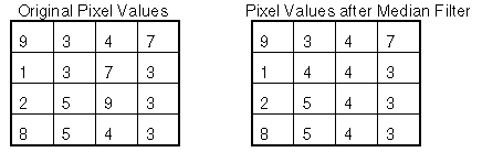
From the example in Figure 1, consider the (2, 2) element. The resulting value is found by taking (9 3 4 1 3 7 2 5 9), sorting them to (1 2 3 3 4 5 7 9 9) and using the fifth element, 4.
The median filter algorithm that this paper describes does a straight copy of the edge pixel values. The interior pixel values are processed eight at a time. This example also assumes the input data is in 8-bit unsigned grayscale values. For these reasons, it is assumed that the image width is on the order of 8n+2. If the image width is different, it is recommended that the C code compensate, since this data would be outside the inner loop and not worth special treatment in the assembler.
When this median filter processes the interior pixel values, it uses several loops to compute the final values. Consider the pseudocode shown in Figure 2. First, it must process each row (line 1). Then, it must process each set of eight values in that row (line 2). For each set of values, the appropriate nine pixel values are loaded (line 3). Then the bubble sort begins: the bubble sort keeps count of the maximum number of items that need to be sorted (line 4), then for each of the items from 0 up to this maximum number (line 5), the eight sets of nine values get sorted and swapped (line 6).

One disadvantage of the implementation of this filter is a number of unaligned memory accesses. These were necessary to load the adjacent pixel values. This is of some concern, since an unaligned access adds three cycles of latency before the result can be used. The good news is that the unaligned memory accesses occur outside of the computationally intensive inner two loops. The net effect after the optimizations described later is that the unaligned penalty is only 1852 out of 794714 cycles.
The bulk of the work and the best opportunity to take advantage of the MMX instructions for this median filter happens when filtering interior pixel values. To get a median value, the filter must consider the current pixel value and the eight adjacent pixel values. Then it must sort them to find the median value.
Sorting is a well researched subject. Because there are only nine values to sort, a bubble sort was selected. While other sort algorithms theoretically behave better (nlogn vs n squared) the difficulty with more advanced sort routines is that n must be much larger than nine before their additional overhead is balanced by their improved performance. The major advantage of the bubble sort is that, in conjunction with MMX instructions, eight consecutive pixel values can be computed simultaneously, as described below. Another advantage is that the nature of the median filter allows quitting from the bubble sort after finding the middle value. The bubble sort assembly code for a median value offers another advantage during the sort because the code only has to store the middle sorted value.
The first thing that must be done for each data set is to load all nine of the values that must be sorted into temporary storage. Although it would be optimal to put all nine values into registers, there are only eight MMX registers. However, having the values loaded sequentially in storage allows the programmer to use a counter as an index to access the data that is needed. Also, memory locations that are frequently used tend to be in the cache so the MMX instructions incur no extra delay. An extra step in the initialization code to align the storage address on an eight byte boundary was taken to avoid unnecessary unaligned accesses. Since the aligned values are on the stack, the code is still reentrant. The only time that unaligned accesses occur is the initial read when copying data to aligned temporary storage. This is unavoidable because the nine data points are positioned relative to the current point, so reading these values results in unaligned accesses. Despite the initial inconvenience, this is still the fastest way to execute this task.
After the nine values are loaded, the SortAndSwap begins. The SortAndSwap part of the code uses MMX registers that hold eight 8-bit values. This phase operates on two registers at a time. Figure 3 illustrates how the SortAndSwap works. First, each register is copied to another register (lines 1 and 2). Then a mask is generated by using PCMPGTB (lines 3 and 4). The mask is used by PAND to leave all the higher values in one register and all the lower values in the other register (lines 5 and 6). The mask is then copied using MOVQ because the following PANDN instructions are destructive to the mask (line 7). All the lower values are then stored in the masks by using PANDN on the original register values (lines 8 and 9). The instruction POR is then used to get all the lower values in one register and all the higher values in another register (lines 10 and 11). This results in two registers with sorted values where the smaller value bubbles down (or to the right).
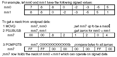
Although this technique is used in this paper, it could not be used directly since the nine values from the input are unsigned data, and there is no unsigned compare instruction in the MMX instruction set. Some method of comparing unsigned data had to devised. One way to do this would have been to use PSUBUSB on the two values being sorted as seen in Figure 4. The PSUBUSB saturates negative differences to zero. This saturation identifies which bytes have a greater or equal unsigned value in MM1 (line 2). Comparing the result of PSUBUSB (line 2) against eight bytes of zeroes using PCMPGTB (line 3) yields a mask. From there, the steps to sort and swap the data are the same as lines 5 through 11 from Figure 3.

Since the subtraction in Figure 3 cannot occur until both registers of eight pixel values have data in the inner loop, this method was not chosen. Rather, the method used in this paper to give the effect of signed data operates outside of the SortAndSwap loop. While the nine values were being read, 128 was subtracted from each byte before it was written to the temporary storage that the sort uses. The subtraction changes all the byte values to signed numbers in such a way that the ordering relation between any two pixels is invariant. Hence, the entire inner loop of the sort can be done using these signed numbers. When the sort is complete and it is time to store the median value, 128 is added back to recover the original pixel values. Because the subtraction is from a static number, the subtraction can be done while loading to temporary storage. Doing this keeps the adjustment for unsigned data out of the innermost loop. This means that this technique has fewer instructions than the technique illustrated in Figure 4, and this is why subtracting 128 was chosen. Subtracting 128 works for this example since the values are only being compared. This would not work in an example where the values needed higher math such as multiplication or division.
The simplest task of this median filter is to copy the edge pixel values. The column edges were copied as the rows were processed to take advantage of having the input and output pointers in the right place at the right time. Two methods were tried to copy the row edges. First, both row edges were copied in the same loop. This way yields just one loop to process both rows. Intuitively, one might think that the writes and reads would pair since they aren't dependent on each other. However, since each of these instructions access memory, they must all be issued in the U-pipe, and hence cannot be paired.
Second, the method was tried where the first row was copied, then the non-edge pixels were processed, and last row was copied. This way avoids having to calculate where the last row begins, and takes advantage of having the input and output pointers much in the right place. Excerpts for each method follow.
Example 1 shows the first way: copy both top and bottom rows in one loop. To copy the bottom row this way, the beginning of the last row must be calculated. This is at nCols*(nRows-1) which gets stored in eax (line 5). Note that the IMUL instruction takes 10 cycles to execute. The number of times that eight 8-bit bytes can be copied gets stored in ebx (line 6). In the loop, two reads from memory and two writes to memory occur to do both the top and bottom rows (lines 8 through 11). Just like the next example, the input and output pointers are advanced, the loop count decrements, and the loop continues until all the pertinent information has been copied (lines 12 through 15).
1 	mov	eax, nRows   	;eax contains nRows
 2 	xor 	edx, edx  	;zero edx for no sign extension on the multiply

 3 	mov 	ebx, nCols   	;ebx contains nCols
 4 	dec 	eax       	;eax contains nRows-1

 5 	imul 	ebx       	;EAX = nCols*(nRows-1) the last row of bitmap

 6 	mov 	ebx, nColSets	;ebx contains the number of sets of 8 in the row

 7_CopyTopAndBottom:

 8	MOVQ	mm0, [ecx]		;get first row value to a register

 9	MOVQ	mm1, [ecx + eax]	;get last row value to a register

10	MOVQ	[edx], mm0		;copy first row value to memory

11	MOVQ	[edx + eax], mm1	;copy last row value to memory

12	add 	ecx, 8   		;advance the pIn pointer
13	add 	edx, 8			;advance the qOut pointer

14 	dec 	ebx			;count the sets of 8 columns done in a row
15jg	CopyTopAndBottom		;if more sets, keep copying by 8's
Example 2 shows the row pixels copied first at the top, then after the non-edge pixels have been processed, the bottom row pixels are copied. Each of these loops, like the loop in Figure 1, needs to set a counter of how many sets of eight are in the row (lines 1 and 12). Unlike the loop in Figure 1, both of these loops do only one read from memory and only one write to memory since only one row is being copied at a time (lines 3 and 4, 14 and 15). Then, again like the loop in Figure 1, the input and output pointers are advanced, the counter decrements, and the rows are copied to completion (lines 5 through 8, 16 through 19).
 1	mov	ebx, nColSets	;ebx contains the number of sets of 8 in a row

 2_CopyTop:
 3	MOVQ	mm0, [ecx]	;get first row value to a register

 4	MOVQ	[edx], mm0	;copy first row value to memory

 5	add	ecx, 8		;advance the pIn pointer
 6	add	edx, 8		;advance the qOut pointer

 7	dec	ebx 		;count the sets of 8 columns done in a row

 8	jg	CopyTop		;if more sets, keep copying by 8's
 9				;
10				;process all of the non-edge pixels...
11				;
12	mov	ebx, nColSets 	;set ebx to the number of columns in the image

13_CopyBottom:
14	MOVQ	mm0, [ecx]	;get first row value to a register

15	MOVQ	[edx], mm0	;copy first row value to memory

16	add	ecx, 8		;advance the pIn pointer
17	add	edx, 8		;advance the qOut pointer

18	dec	ebx		;count the sets of 8 columns done in a row
19	jg	_CopyBottom	;if more sets, keep copying by 8's
For the example used to code this median filter, it was advantageous to copy the bottom row after the inner pixels had been processed. The key instruction that was eliminated with this method was the ten cycle IMUL instruction needed to gain access to the bottom of the array. It is expected that this advantage would diminish with images of increasing width.
Another method of copying the edge rows would be to copy both the top and bottom after the inner pixel value processing. This method avoids the IMUL instruction. But, this method requires that the code track two input pointers and two output pointers, ensure that the input came from the correct area of memory, and that the output pointers write to the correct area of memory.
One optimization is to sort not just from the top down, but to sort the top half and the bottom half of the nine values at the same time, and compare the result. This will potentially allow better pairing, since the top half and the bottom half sorts have no data in common; so they would have no data dependency pipe stalls. Before we could apply this technique however, the code must be modified in the SortAndSwap sections only four registers are required (perhaps by using memory for one of the operands). Since there are nine of twenty cycles without paired instructions in this section, this would be a great exercise for the reader.
Another idea for further optimization is to unroll the SortAndSwap loop into the Load9Pixels loop. Usually for loop unrolling, the programmer needs to set one loop variable according to what was unrolled before jumping to the rest of the loop. Note that to unroll a bubble sort, two variables indicating loop boundaries must be set instead of the typical one. These are for the declining maximum and iterations up to the maximum (here, ebx< and esi) for the bubble sort. Again, it was not done because the instructions in Load9Pixels perform well enough for this example.
Performance for this example is measured in cycles per pixel. The C instructions used to take this measurement can be found in Appendix B. The C code took 1598 cycles per pixel. The MMX instructions used 415 cycles per pixel.
APPENDIX A. CODE LISTING
INCLUDE iammx.inc

    TITLE   MedianFilterMMX
	.486P
.model FLAT

;Global DATA segment
_DATA   SEGMENT
signOffset DWORD 2 DUP (80808080h)
_DATA	ENDS

_TEXT	SEGMENT

_s1Ptr$  = 16
_s2Ptr$  = 20
_size$   = 24
_resPtr$ = 28
PUBLIC  median_mmx

median_mmx PROC C USES ebx ecx edx esi,
pIn:PTR DWORD,  			;pointer to input array
qOut:PTR DWORD, 			;pointer to output array
nRows:DWORD,    			;DWORD of number of Rows
nCols:DWORD     			;DWORD of number of Columns
;
; declare local variables
;
    LOCAL nColSets:DWORD    		;number of sets of 8 in a column
    LOCAL nColCnt:DWORD     		;counter for the sets in a column
    LOCAL nLoad9[20]:DWORD  		;temporary space for 9 pixel values
    LOCAL ptrLoad9:DWORD    		;aligned pointer for 9 pixel values


;    int     3
    mov  	ebx, nCols      	;ebx contains nCols
    lea  	esi, nLoad9     	;esi is address of nLoad9

    mov  	ecx, pIn        	;ecx contains pIn
    add  	esi, 7          	;add 7 to address of nLoad9

    shr  	ebx, 3          	;shift left 3 AKA divide by 8
    mov  	edx, qOut       	;edx points to qOut

    mov  	nColSets, ebx   	;save the col sets in nColSets
    and  	esi, 0fffffff8h 	;align the address for the pointer
                            		;to 9 pixel values

    mov  	nColCnt, ebx    	;save the col sets in nColSets
    mov  	ptrLoad9, esi   	;move the aligned address into ptrLoad9

;;COPY THE TOP ROW VALUES WITHOUT CHANGE
;;Use ebx which is already loaded with the sets of 8
;;in a column as the counter for the loop
_CopyTop:
    MOVQ 	mm0, [ecx]      	;get first row value to a register

    MOVQ 	[edx], mm0      	;copy first row value to memory

    add  	ecx, 8          	;advance the pIn pointer
    add  	edx, 8          	;advance the qOut pointer

    dec  	ebx             	;decrement the count the sets done in a row
    jg     	CopyTop        		;if more to copy, then keep copying


    mov  	esi, [ecx]      	;copy last 2 of first row and 1st of next row 8bit
    mov  	ebx, nRows      	;use ebx to set up nRows to count the inner rows

    mov  	[edx], esi      	;copy the last 3 (well, 4) top row values to qOut
    sub  	ebx, 2          	;decrement nRows by 2 since top & bottom
					;aren't computed

    mov  	nRows, ebx      	;get nRows = nRows - 2
    add  	ecx, 3          	;advance the pIn pointer

    MOVQ 	mm6, signOffset 	;let mm6 hold the value 128 in each byte
    add  	edx, 3       		;advance the qOut pointer

;PROCESSING THE INNER PIXELS BEGINS
;Thru_Rows goes across the rows in sets of 8 pixels
;Another register would be really nice....
_ThruRows:
    mov  	ebx, nColSets		;get the value of nColSets into a register

    mov  	nColCnt, ebx  		;get the value of nColSets into nColCnt

;Load9Pixels does the loading of the 9 pixel values into temporary
;storage. It also does the subtract by 128 to in effect "sign" the data.
_Load9Pixels:
    mov  	ebx, nCols    		;ebx contains nCols
    mov  	esi, ecx      		;esi contains value of pIn

    mov  	eax, ptrLoad9  		;let eax point to the aligned address for temporary storage
    sub  	esi, ebx       		;esi = ecx(pIn) - ebx(nCols) to allow reading the pixels above

    MOVQ 	mm0, [ecx - 1] 		;Left pixels from memory

    MOVQ 	mm1, [ecx]     		;Center pixels from memory

    MOVQ 	mm2, [ecx + 1] 		;Right pixels from memory
    PSUBB	mm0, mm6       		;Left pixels minus 128

    MOVQ 	mm3, [esi - 1] 		;Upper Left-hand pixels from memory
    PSUBB	mm1, mm6       		;Center pixels minus 128

    MOVQ 	mm4, [esi]     		;Upper Center pixels from memory
    PSUBB	mm2, mm6       		;Right pixels minus 128

    MOVQ 	[eax + 24], mm0 	;move "signed" Left pixels to eax
    PSUBB	mm3, mm6       		;Upper Left-hand pixel minus 128

    MOVQ  	[eax + 32], mm1 	;move "signed" Center pixels to eax
    PSUBB	mm4, mm6       		;Upper Center pixel minus 128

    MOVQ 	[eax + 40], mm2 	;move "signed" Right pixels to eax

    MOVQ 	[eax], mm3      	;move "signed" Upper Left-hand pixels to eax

    MOVQ 	[eax + 8], mm4 	 	;move "signed" Upper Center pixels to eax

    MOVQ 	mm0, [esi + 1]  	;Upper Right pixels from memory

    MOVQ 	mm1, [ecx + ebx - 1]	;Lower Left pixels from memory

    MOVQ 	mm2, [ecx + ebx]  	;Lower Center pixels from memory
    PSUBB 	mm0, mm6          	;Upper Right pixels minus 128

    MOVQ 	mm3, [ecx + ebx + 1] 	;Lower Right pixels from memory
    PSUBB	mm1, mm6          	;Lower Left pixels minus 128

    MOVQ 	[eax + 16], mm0  	;move "signed" Upper Right pixels to eax
    PSUBB	mm2, mm6         	;Lower Center pixels minus 128

    MOVQ  	[eax + 48], mm1  	;move "signed" Lower Left pixels to eax
    PSUBB	mm3, mm6         	;Lower Right pixels minus 128


    MOVQ 	[eax + 56], mm2  	;move "signed" Lower Center pixels to eax
    MOVQ 	[eax + 64], mm3  	;move "signed" Lower Right pixels to eax

;Place holder for setting ebx at the maximum for number of registers
;to be sorted
;_DowntoCheckTil:
    mov  	ebx, 8           	;ebx contains the max number of registers to sort

;UptoCheckTil takes the sort from 0 upto max, where max is ebx which
;represents how many times the sort has been bubbled through.
_UptoCheckTil:
    mov  	esi, ebx         	;set esi to the max for this sort
    mov  	eax, ptrLoad9    	;reset eax at the top of the registers to sort

    MOVQ 	mm0, [eax]       	;move the first values at eax into mm0

;SortAndSwap does just that -- sorts and swaps. It expects mm0 to already
;be holding the first set of 8 values to sort. This is *the* innermost
;loop that should really take time to be optimized.
_SortAndSwap:
    MOVQ 	mm1, [eax + 8]   	;move the 2nd set of 8 values to sort into mm1

    MOVQ 	mm2, mm0         	;duplicate the values of mm0
    MOVQ 	mm3, mm1         	;duplicate the values of mm1

    MOVQ 	mm7, mm0         	;set mm7 up to be the mask
    PCMPGTB	mm7, mm1         	;mm7 is a mask of mm0 > mm1

    PAND 	mm1, mm7         	;mm1 is all the lower values
    PAND 	mm0, mm7         	;mm0 is all the higher values

    MOVQ 	mm5, mm7         	;copy the mask since the upcoming
					;PANDN's are destructive to it
    PANDN	mm7, mm3         	;mm7 is all the higher values of mm1

    PANDN	mm5, mm2         	;mm5 is all the lower values of mm0
    POR  	mm0, mm7         	;mm0 is all the higher values of mm0 & mm1

    POR  	mm1, mm5         	;mm1 is all the lower values of mm0 & mm1
    MOVQ 	[eax], mm0       	;replace the higher values to temporary storage

    MOVQ 	mm0, mm1         	;set mm0 up with the next lower register to
					;prep for the next loop
    add  	eax, 8           	;advance the pointer of temporary storage

    dec  	esi              	;decrement the upto counter
    jg    	SortAndSwap     	;if more to sort, sort it

    dec 	ebx              	;decrement the downto counter
    cmp  	ebx, 4           	;compare counter to midway point

    jge  	_UptoCheckTil    	;if more to sort, sort it

    PADDB	mm0, mm6         	;Median plus 128 to restore original value
    add  	ecx, 8           	;advance input pointer

    MOVQ 	[edx], mm0       	;store the Median Value to output
    add  	edx, 8           	;advance output pointer

    dec  	nColCnt          	;decrement the column counter
    jg   	_Load9Pixels     	;if more pixels to compute in this row, compute them

    ;Reached the end of a row. Copy the column edges before computing the
    ;next inner pixel values. Although 4 8bit values are copied over, since
    ;the input and output pointers are only advanced by 2, then the last two
    ;values will be overwritten. This saves a 2 cycle hit for switching to
    ;16 bit mode from 32 bit mode.
    mov  	eax, [ecx]       	;move 4 8bit values to eax
    add  	ecx, 2           	;advance the input pointer by 2


    mov  	[edx], eax       	;move 4 8bit values to output
    add  	edx, 2           	;advance the output pointer by 2

    dec  	nRows            	;decrement the row count
    jg   	_ThruRows        	;if more rows to compute, compute them


    ;All done processing inner pixels. Now its time to copy the bottom
    ;row pixels. The input and output pointers are backed up one so that
    ;the last two values to copy can be done in 16 bit mode without
    ;going out of the array bounds.
    dec  	ecx              	;back up the input pointer
    dec  	edx              	;back up the output pointer

    mov  	ebx, nColSets    	;reset ebx to be the counter of sets of 8

_CopyBottom:
    MOVQ 	mm0, [ecx]       	;copy data from memory

    MOVQ 	[edx], mm0       	;copy data to memory

    add  	ecx, 8           	;advance the input pointer
    add  	edx, 8           	;advance the output pointer

    dec  	ebx              	;decrement the counter
    jg   	_CopyBottom       	;if more to copy, copy it

    mov  	bx, [ecx]        	;copy last 2 values from memory

    mov  	[edx], bx        	;copy last 2 values to memory

;    int     3
    emms                      	;DONE! flush the registers
    ret     0
median_mmx ENDP
_TEXT	ENDS
END
APPENDIX B. C LANGUAGE CODE LISTING
/*
* * MEDIAN C
*    median_C - use C code to implement a Median Filter
*/

void median_C (BYTE TextureMap[],
               BYTE qOut_C[],
               long height,
               long width)
{
    LONG nLastRow;
    LONG nLastCol;
    BYTE nSort[9];
    int i, j, k;

        nLastCol = width - 1;
        nLastRow = height - 1;

        //copy the top and bottom rows into the result array
        for (i=0; i<width; i++) {
            qOut_C[i] = TextureMap[i];
            qOut_C[nLastRow * width + i] = TextureMap[nLastRow * width + i];
        }
		qOut_C[i] = TextureMap[i];


        nLastCol--;
        nLastRow--;

        /* process the interior pixels */
        i = width + 1;
		for (k=0; k < nLastRow; k++)
		    {
			for (j=0; j < nLastCol; j++, i++)
			    {
            	nSort[0] = TextureMap[i-width-1];
            	nSort[1] = TextureMap[i-width];
            	nSort[2] = TextureMap[i-width+1];
            	nSort[3] = TextureMap[i-1];
            	nSort[4] = TextureMap[i];
            	nSort[5] = TextureMap[i+1];
            	nSort[6] = TextureMap[i+width-1];
            	nSort[7] = TextureMap[i+width];
            	nSort[8] = TextureMap[i+width+1];
            	Sort (nSort);
            	qOut_C[i] = nSort[4];
        		}
			qOut_C[i] = TextureMap[i++];
			qOut_C[i] = TextureMap[i++];
			}
        qOut_C[i] = TextureMap[i++];
