
| Disclaimer Information in this document is provided in connection with Intel products. No license, express or implied, by estoppel or otherwise, to any intellectual property rights is granted by this document. Except as provided in Intel's Terms and Conditions of Sale for such products, Intel assumes no liability whatsoever, and Intel disclaims any express or implied warranty, relating to sale and/or use of Intel products including liability or warranties relating to fitness for a particular purpose, merchantability, or infringement of any patent, copyright or other intellectual property right. Intel products are not intended for use in medical, life saving, or life sustaining applications. Intel may make changes to specifications and product descriptions at any time, without notice. Copyright © Intel Corporation (1996). Third-party brands and names are the property of their respective owners.
|
The Intel Architecture (IA) media extensions include single-instruction, multi-data (SIMD) instructions. This application note presents examples of code that exploit these instructions. Specifically, the levinsonmmx function presented here illustrates how to use the new MMX technology multiply-and-add instruction (PMADDWD) to perform matrix multiplication more efficiently. The performance improvement relative to traditional IA code is due to the ability to efficiently perform multiple multiply-and add operations in fewer cycles. To perform a signed Q15 multiply-and-add would use two IA instructions, IMUL and ADD, and would take as many as 13 cycles. Using the MMX technology PMADDWD instruction, you can perform four word multiplies and two doubleword adds in three cycles. Performance gain can also be attributed to the fact that the MMX instructions operate on packed 64-bit values instead of 32-bit values.
The amount of data which represents a human voice or sound is usually too large to store on a typical PC. Therefore, encoding the sound and storing only a partial set of the data would be more practical. Voice encoding is one of the applications in which the Levinson-Durbin algorithm is used. This algorithm generates both a set of prediction coefficients and reflection coefficients in a recursive manner as follows:
am = Km = -  r(m) + rbm-1am-1
            	    ------------------
                    r(0) + rbm-1abm-1

am(k)  = am-1(k) + Kmam-1(m-k)  k = 1, 2, ..., m - 1
			     m = 1, 2, ..., p

where a is the prediction coefficient array, K is the reflection coefficient array,
and r is the input vector.
Note: The superscript b denotes the vector with elements taken in reverse order.
The integer algorithm consists of three sections:
The input and output of this version of the Levinson-Durbin algorithm is represented in fixed-point notation. The input matrix r[ ] and the resultant reflection coefficients k[ ] are represented as Q15 fractions stored in an array of short integers of size m. The prediction coefficients a[ ] are represented as Q13 fractions also stored in an array of short integers of size m. If two (2) signed Q15 fractions are multiplied together, the result will be a Q30 signed fraction. If a Q15 signed fraction is multiplied by a Q13 signed fraction, the result is a Q28 signed fraction. To determine the number of bits assigned to the fractional part of the result of a multiplication, add the number of bits assigned to the fractional parts of each multiplicand. To determine the number of bits assigned to the fractional part of the result of a division, subtract the number of bits assigned to the denominator from the number of bits assigned to the numerator. Refer to Figure 1 for further clarification.
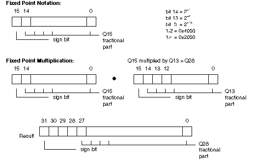
There are various areas in this algorithm where errors can occur. These errors are due to noise in the input data and performing integer instead of floating-point arithmetic. This version of the Levinson-Durbin algorithm performs two error correction techniques to minimize the overall amount of error found in the output results. The first technique minimizes the error introduced by using integer arithmetic. This is accomplished by rounding results to the nearest digit of precision prior to converting from one precision to another (i.e. Q28 to Q13). Refer to Example 2 for a graphical representation of fixed point conversion techniques.
Converting from a Q28 to a Q13 signed fraction:

0x0A234238	Q28 signed fraction
+ 0x00004000	rounding factor
0x0A238238	rounded result
>> 15
0x00001447	conversion result
The second technique brings a set of input data back into a usable range for the Levinson-Durbin algorithm. Input data can be determined to be not stable if any of the reflection coefficients produced are greater than one. To stabilize the input data, a scaling factor was used to scale both the prediction and reflection coefficients. This number may vary across applications and may need to be modified. For the system which was used to verify the MMX code optimized Levinson-Durbin algorithm, the appropriate scaling factor was was 0x7ff8.
There were numerous areas within the Levinson-Durbin algorithm which could be easily adapted and optimized for use with the MMX instruction set. There was also one area which could not. The remainder of this section discusses each part of the Levinson-Durbin algorithm and the optimizations and MMX technology tricks used during programming.
The formulas used to calculate Rn and Rd are as follows:
			Rn = r(m-i)*a(i)			for i=0 to m-1
			Rd = r(i)*a(i)			for i=0 to m-1

where r() is the input matrix and a() is the prediction coefficient matrix.
These formulas are simple vector multiplications, but when using strictly IA integer instructions may take many cycles to calculate. The MMX instruction set supplies a multiply-add instruction (PMADDWD) which performs four word multiplies and two double-word adds in three cycles. This instruction can be pipelined with any MMX instruction, including another PMADDWD instruction. The result of a PMADDWD instruction can only be used by other instructions issued three clocks later. If it is used prior to the three clock latency, a stall will occur until the result is ready.
The inner loop which calculates Rn and Rd uses the PMADDWD instruction to perform four word multiplies and two doubleword adds for Rn and Rd with each iteration. The result of each multiply and add instruction is two doubleword Q28 signed fixed point fractions stored in MM0 (Rd) and MM2 (Rn). Each of these values must be added to an accumulator, which keeps a running summation of the current result (MM6 is used for Rd and MM7 is used for Rn).
In order to use the PMADDWD instruction within the inner loop to perform four word multiplies and two doubleword adds, two assumptions were made. The first is that the prediction coefficient array is initialized to zero. This prevents incorrect results for calculations of Rn and Rd which include three or fewer input values. The second is that the size (in bytes) of both the input vector and the prediction coefficient vector must be divisible by eight. This is to prevent reading past the end of either vector since four input values are read for each iteration of the loop.
Example 4 contains the code for the inner loop of the Levinson-Durbin algorithm.
calcRnRd:
1. 	movq		mm2,	[edx][eax*2]	; get the next 4 rT() matrix entries
2. 	pmaddwd		mm0,	mm1		; calculate (r(i) * a(i)) + (r(i+1) *
						; a(i+1)) and (r(i+2) * a(i+2)) +
						; (r(i+3) * a(i+3))
	add		eax,
3. 	; increment the aMatrix address

4. 	pmaddwd		mm2,	mm1		; calculate (rT(i) * a(i)) + (rT(i+1) *

						; a(i+1)) and (rT(i+2) * a(i+2)) +
						; (rT(i+3) * a(i+3))

5.						; Two penalties occur during this clock
6.						; cycle.  The first is a pmaddwd stall
						; since the instruction on line 8 uses
						; the result of the pmaddwd instruction
						; issued on line 2.  The second penalty
						; occurs because eax is incremented on
						; line 3 and used the next cycle.

7.	movq		mm1,	[ecx][eax*2]	; get the next 4 a() matrix entries
8.	paddd		mm6,	mm0		; accumulate Rd

9.	movq		mm0,	[esi][eax*2]	; get the next 4 r() matrix entries
10.	paddd		mm7,	mm2		; accumulate Rn

11.	cmp		eax,	ebx		; compare i and m
12.	jl		calcRnRd		; if (i < m) then keep incrementally
						; calculating Rn and Rd
Assuming all data is present in the data cache, the inner loop which calculates Rn and Rd varies in the number of cycles it takes to execute. If the data being read from the reverse input matrix is aligned, no penalty is incurred and the loop executes in six cycles per pass. If the data being read is unaligned, the read incurs a three cycle penalty, increasing the overall loop time from six to nine cycles per pass. Data alignment is extremely critical to the number of cycles in which the loop executes. If the input matrix and the prediction coefficient matrix are not aligned on quad word boundaries, accesses to these matrices will also incur an unaligned penalty of three clock cycles.
Within the inner loop is a one clock cycle penalty which is caused by two violations of the pairing rules. The first penalty occurs on line 7 where a quad word move is issued. This instruction uses the EAX register to generate an index into the a matrix. Exactly one cycle prior to issuing the MOVQ instruction, EAX was used as a destination register on line 3. Pairing rules state that any integer register can not be used to address memory for two clocks after it has been modified. This is referred to as an address generation interlock (AGI). Therefore a penalty of one clock cycle is incurred. The second penalty occurs on line 8 where a packed add is issued. This instruction uses MM0 as an operand. MM0 contains the result of the PMADDWD instruction issued on line 2. Pairing rules state that the result of a multiply instruction can only be used by other instructions issued three clocks later. Therefore, a penalty of one clock cycle is incurred. Since both penalties occur in the same cycle, only a one clock cycle stall occurs instead of two.
This loop was optimized to support efficient calculations of both the prediction and reflection coefficients to an order of 10. For orders of 16 or greater, this loop can be optimized even further by unrolling the loop one more time. This would be done by performing eight word multiplies and four doubleword adds for both Rn and Rd each time through the loop. It would eliminate half of the loop overhead and may also have the potential of hiding the multiply-add and AGI pipe stall at instruction 8. See Example 5 for an example.
calcRnRd:
1.	movq		mm2,	[edx][eax*2]	; get the next 4 rT() matrix entries
2.	pmaddwd	mm0,	 mm1			; calculate (r(i) * a(i)) + (r(i+1) *
						; a(i+1)) and (r(i+2) * a(i+2)) +
						; (r(i+3) * a(i+3))

3.	movq		mm3,	8[edx][eax*2]	; get the next 4 rT() matrix entries
4.	pmaddwd	mm2, 	mm1			; calculate (rT(i) * a(i)) + (rT(i+1) *
						; a(i+1)) and (rT(i+2) * a(i+2)) +
						; (rT(i+3) * a(i+3))

7.	movq		mm1,	8[ecx][eax*2]	; get the next 4 a() matrix entries
8.	paddd		mm6,	 mm0		; accumulate Rd

9.	movq		mm4,	8[esi][eax*2]	; get the next 4 r() matrix entries
10.	pmaddwd	mm3, 	mm1			; calculate (r(i+4) * a(i+4)) + (r(i+5)*
						; a(i+5)) + (r(i+6) * a(i+6)) + (r(i+7)*
						; a(i+7))

11.	movq		mm0,	[esi][eax*2]	; get the next 4 r() matrix elements
12.	pmaddwd	mm4,	mm1			; calculate (rT(i+4)*a(i+4)) + (rT(i+5)
						; * a(i+5)) + (rT(i+6) * a(i+6)) +
						; (rT(i+7) + a(i+7))

13.	movq		mm1,	[ecx][eax*2]	; get the next 4 a() matrix elements
14.	paddd		mm7,	 mm2		; accumulate Rn

15.	add		eax,	8		; add 8 elements to the eax index
16.	paddd		mm6,	mm3		; accumulate Rd

17.	paddd		mm7, 	mm4		; accumulate Rn

18.	cmp		eax,	ebx		; compare i and m
19.	jl		calcRnRd		; if (i < m) then keep incrementally
						; calculating Rn and Rd
The formula to compute Rn uses the values of the input vector in the reverse order. Three options were considered when deciding how to obtain this vector:
Option 3 was chosen since this read/store operation could be paired with other non-paired instructions prior to executing the inner loop. Therefore, the reverse of the input matrix was obtained "free." Both options 1 and 2 were investigated and discarded because of the extra cycles added to the overall performance of the code. Option 1 added extra instructions and loop overhead to the function. Option 2 added extra cycles within the inner loop to rearrange data appropriately for the calculation of Rn.
After the execution of the inner loop, Rn and Rd have their results accumulated in MM7 and MM6, respectively. These registers each have two doubleword Q28 signed fractions which need to be separated and added together to obtain the final result. A copy of each accumulator is made and then the packed-shift-right-logical-quad (PSRLQ) instruction is used to shift the high doubleword into the low doubleword position. This is added to the accumulator to obtain the final Rn and Rd result in the low doubleword position. Refer to Example 6 for a code example. In this example, there are also statements which get the data ready for the division in the next code segment. This includes negating Rn and clearing registers MM3 and MM0.
calcnew_A:
1.	movq	mm0, mm6		; make a copy of the partial Rd
2.	movq	mm1, mm7		; make a copy of the partial Rn

3.	movd	mm4, round_factor	; load the rounding factor for later
4.	psrlq	mm1, 32			; put the high doubleword of Rn into
						; the low doubleword position
5.	paddd	mm7, mm1		; do the final Rn calculation
6.	pxor	mm3, mm3		; zero out mm3 to negate Rn for the
						; divide

7.	psubd	mm3, mm7		; negate Rn prior to the divide
8.	psrlq	mm0, 32			; put the high doubleword of Rd into
						; the low doubleword position

9.	paddd	mm6, mm0		; do the final Rd calculation
10.	pxor	mm1, mm1		; zero out mm1 for unpacking the
						; rounding factor later
The mth order reflection and prediction coefficients are calculated by dividing Rn by Rd. This integer division can not be avoided since the denominator changes for each iteration of the main loop. It takes 43 clock cycles every time that it is executed. If the denominator value remained constant with each iteration of the outer loop, one divide could have been executed prior to entering the main loop to determine 1/Rd. This value could then be used in an integer multiplication using the IMUL instruction and would take 10 cycles to execute. The IMUL instruction would have to be used in this instance since the MMX instruction set does not supply a doubleword multiply instruction. A floating point divide could also be executed in place of the fixed point integer divide, but would incur a 100 clock cycle penalty of switching from floating point code to MMX code. Therefore it was not used.
This segment of code recalculates the prediction coefficients from 0 through m-1 based on the newly calculated mth coefficient. The pseudocode is as follows:
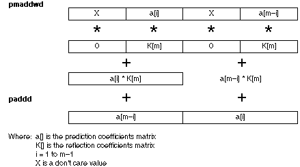
				for	( i = 1; i < m; i++)
					b[i] = a[i] + (K[m] * a[m-i]);

				for	( i = 1; i < m; i++)
					a[i] = b[i];
To avoid needing the temporary array b, the MMX code calculates both the new a[i] and a[m-i] with each iteration of the loop. The MMX instruction set does not implicitly provide a double-word multiply. Therefore, the PMADDWD instruction was used. Refer to Figure 2 for a graphical representation of the data setup. After the data has been setup, the instruction PMADDWD MM0, MM2 is issued to calculate K[m]*a[i] and K[m]*a[m-i]. The result of this multiply-add is a Q28 signed fraction. It is then added to MM3, which contains a[i] in the low doubleword and a[m-i] in the high doubleword, each represented as Q28 signed fractions. This addition obtains the new a[i] and a[m-i] values.
An approximate overall performance of this version of the Levinson-Durbin algorithm can be calculated based on the performance of three sections of the code: the calculation of Rn and Rd, the calculation of K[m], and the re-calculation of the prediction coefficients. The following discussion about performance assumes all data is present in the data cache and that all data is properly aligned.
There are two cycle count numbers which are important to take into consideration when approximating the number of cycles it takes to calculate Rn and Rd. When accesses to the reverse of the input vector are aligned, it takes six clock cycles per iteration to multiply and accumulate four values for both Rn and Rd. When accesses to the reverse of the input vector are unaligned, it takes nine clock cycles per iteration. Since half of all accesses to the reverse of the input vector are aligned and half are unaligned, on average it takes 7.5 cycles to calculate four values for both Rn and Rd or .9375 clock cycles for one value.
To calculate a[m] and K[m] and to set up register values prior to re-calculating the prediction coefficients takes approximately 64 clock cycles. The majority of these cycles can be directly attributed to the integer divide which executes in 43 clock cycles. As mentioned previously, this integer divide can not be avoided.
For the re-calculation of the prediction coefficients, there are two cycle count numbers which must be taken into consideration. When accesses to the prediction coefficient array are aligned, it takes 14 clock cycles to recalculate two elements. When accesses to the prediction coefficient array are unaligned, it takes 20 clock cycles to recalculate two elements. Since half of all accesses to the prediction coefficient array are aligned and half are unaligned, on average it takes 17 cycles to recalculate two elements or 8.5 clock cycles to recalculate one.
Applying these cycle count numbers to an application which calculates pSize reflection coefficients using an input vector of size pSize+1, an approximate overall performance can be obtained as follows:
For the C language version of the Levinson-Durbin algorithm, refer to Appendix A. For the complete MMX code optimized version of the Levinson-Durbin algorithm, refer to Appendix B.
The MMX code optimized version is reentrant but the user may wish to dispose of the local variables and pass them in as arguments to the procedure if stack usage is an issue.
APPENDIX A: "C' Version of the Levinson-Durbin Algorithm
/ *********************************************************************************
* Description:
 *	Levinson-Durbin is the scalar (not MMX code) version of the Levinson-Durbin
 *	algorithm. It is used to calculate the reflection and prediction coefficients of
 *	a given set of normal equations.
 *
 * Inputs:
 *	r	short int *		a pointer to the first element
 *					of the input 'r' matrix
 *	a	short int *		a pointer to the output
 *					prediction coefficients array
 *	k	short int *		a pointer to the output
 *					reflection coefficients array
 *	p	short int		the number of reflection coefficients
 *					to solve for (typically 10 or 16).
 *
*********************************************************************************/
void Levinson_Durbin (short *r, short a*, short *k, short p)
{   // begin Levinson_Durbin()
short i,			// inner loop index
	m,			// outer loop index
	b[11];			// temporary vector to store the prediction coefficients
long Rn,			// inner loop numerator accumulator
	Rd,			// inner loop denominator accumulator
	temp;			// temporary variable used for intermediate result calculations

	// initialize a[0] to 1/4
	a[0] = 8192;

	// For each order, calculate a new prediction and reflection coefficient
	for (m = 1; m < p + 1; m++)
		 {

		// Initialize the numerator and denominator accumulators to zero
		Rn = Rd = 0;

		// Calculate the numerator and denominator values for the integer division
		for (i = 0; i < m; i++)
			  {
			  Rn = Rn + (r[m-1] * (long)a[i]);
			  Rd = Rd + (r[i] * (long)a[i]);
			  }

		// Calculate the reflection coefficient k[m]. Round the Q28 number prior
		// to converting it to a Q15 number. Also, scale it by the scaling factor
		// to help keep the input data in proper range.
		k[m] = -Rn / ((Rd + 0x4000) >> 15);
		k[m] = (((long)k[m] * 0x7ff8) + 0x4000) >> 15;

		// Calculate the new prediction coefficient by converting k[m] from
		// a Q15 to a Q13 number
		b[m] = (k[m] + 0x2) >> 2;

		// Calculate the new prediction coefficients for the next iteration
		for (i = 1; i < m; i++)
		b[m] = (((long)a[i] << 15) + (k[m] * (long)a[m-i]) + 0x4000) >> 15);

		// Copy the prediction coefficients from the temporary b[] array to a[]
		for ( i = 1; i < m+1; i++)
			a[i] = b[i];
		}

}   // end Levinson_Durbin()
APPENDIX B: The MMX™ Technology Version of the Levinson-Durbin Algorithm
;***************************************************************************/
;* Description:
;*	The purpose of this file is to provide the MMX code for the
;*	levinson-durbin algorithm as an instructional example to those who
;*	are just beginning to code using MMX instructions.
;*
;* Assumptions:
;*	1.	The set of normal equations given are stable
;*	2.	The output matrix 'a' containing the prediction coefficients
;*		is initialized to all 0's.
;*	3.	The normal equations are represented by one matrix 'r' which
;*		contains the coefficients gamma(0) through gamma(p) given as
;*		Q15 signed short integers.
;*	4.	The resultant reflection coefficients will be returned as
;*		Q15 signed short integers.
;*	5.	The resultant prediction coefficients will be returned as
;*		Q13 signed short integers.
;*	6.	The rTmatrix defined below is of size (p*2) + 16 bytes.
;****************************************************************************/
;* 			    TEXT SEGMENT
;****************************************************************************
_TEXT	SEGMENT

;
; Declare levinson_mmx as a public routine to allow the 'C' code to
; call it.
;
PUBLIC levinson_mmx

;***************************************************************************/
;*	_levinson_mmx is the MMX optimized code version of the Levinson-Durbin
;*	algorithm.  It is used to calculate the reflection coefficients of
;*	a given set of normal equations.
;*
;* Inputs:
;*	rPtr	short int *		a pointer to the first element
;*					of the input 'r' matrix
;*	aPtr	short int *		a pointer to the output
;*					prediction coefficients array
;*	kPtr	short int *		a pointer to the output
;*					reflection coefficients array
;*	pSize	short int		the number of reflection coefficients
;*					to solve for (typically 10 or 16).
;*
;****************************************************************************/
levinson_mmx PROC C USES ebx ecx edx esi,
rMatrix:PTR WORD,
aMatrix:PTR WORD,
kMatrix:PTR WORD,
pSize:DWORD
;
; Declare local variables
;		1. rTmatrix     - used to store the reverse of rMatrix
;		2. rTindex      - used to store the rTmatrix index
;		3. mSave        - used to store the loop counter 'm'
;		4. round_factor - contains the rounding factor 0x4000
;		5. scale_factor - contains the scaling factor 0x7ff8
;
	LOCAL	rTmatrix[72]:WORD
	LOCAL	rTindex:DWORD
	LOCAL	mSave:DWORD
	LOCAL	round_factor:DWORD
	LOCAL	scale_factor:DWORD

;
; This section of code initializes the local variables round_factor and scale_factor
; and sets up some of the items which need to be done prior to executing the algorithm
;
	mov		round_factor, 4000H		; initialize the rounding factor
	mov		eax, pSize			; get the value of 'p'

	mov		scale_factor, 7ff8H		; initialize the scaling factor
	mov		esi, aMatrix			; get the pointer to the 'a' matrix

	mov		WORD PTR [esi], 2000H		; store the scaling element into a[0]
	lea		edx, rTmatrix[eax*2]		; get the first rTmatrix index address

	mov		rTindex, edx			; save the first rTmatrix address
	mov		ebx, 1				; initialize the main loop counter 'm'
;
; This section of code sets up the pointer to
; the input array 'r' and rTmatrix used to calculate Rn and Rd.  It also
; performs the test:
;	while (p >= m)
;
_levinson_outer_loop:
	mov		esi, rMatrix			; initialize the rMatrix pointer
	cmp		eax, ebx			; is (p >= m) ?

	mov		ecx, [esi][ebx*2]		; get the next rMatrix element
	jl		_levinson_done			; if (p < m) we are done!

;
; This section of code sets up registers used to calculate Rn and Rd.  It also
; incrementally builds the rTmatrix with each iteration of the main levinson loop,
; adding one more rMatrix element to the front of the array.  The reverse of the
; input matrix 'r' is needed when calculating Rn. Rn uses the elements 1 to m of
; rMatrix in reverse as one of the multiplicands with aMatrix elements as the other.
;
_setup_RnRd_calc:
	mov 		eax, 0				; initialize the loop counter to 0

	mov		[edx], cx			; store the next rTmatrix element
	mov		ecx, aMatrix			; get the pointer to the 'a' matrix

	movq		mm0, [esi]			; get the first quad word of 'r'
	pxor		mm6, mm6			; initialize Rd to 0

	movq		mm1, [ecx]			; get the first quad word of aMatrix
	pxor		mm7, mm7			; initialize Rn to 0

	cmp		eax, ebx			; is (i < m) ?
	jge		_calc_new_A			; if not, calculate Rn and Rd

;
; This section of code calculates Rn and Rd.  The calculation used is:
;	while (i < m) {
;		Rn = Rn + (rTmatrix[i]*aMatrix[i]);
;		Rd = Rd + (rMatrix[i+1]*aMatrix[i]);
;		}
; where Rn and Rd are long, Q28 signed fractions, rTmatrix,
; and rMatrix are short, Q15 signed fractions and aMatrix contains
; short, Q13 signed fractions. Up to 4 multiply/adds are done at a time
; for both Rn and Rd.
;
_calc_RnRd:
	movq		mm2, [edx][eax*2]	; get the next quad word of rTmatrix
	pmaddwd		mm0, mm1		; calculate 'r' * aMatrix quad multiply/add

	add		eax, 4			; increment the loop counter
	pmaddwd		mm2, mm1		; calculate rTmatrix * aMatrix quad mul/add

	movq		mm1, [ecx][eax*2]	; get the next aMatrix quad word
	paddd		mm6, mm0		; Rd = Rd + (rMatrix * aMatrix) quad word

	movq		mm0, [esi][eax*2]	; get the next rMatrix quad word
	paddd		mm7, mm2		; Rn = Rn + (rTmatrix * aMatrix) quad word

	cmp		eax, ebx		; is (i < m)?
	jl		_calc_RnRd		; if so, then keep incrementally calculating
						; Rn and Rd

;
; Upon leaving the loop that calculates Rn and Rd, Rd (mm6) and Rn (mm7) contain two long,
; signed Q28 fractions which need to be added together to get the final Rn
; and Rd result. This code performs this calculation.
;
_calc_new_A:
	movq		mm0, mm6		; make a copy of the partial Rd result
	movq		mm1, mm7		; make a copy of the partial Rn result

	movd		mm4, round_factor	; load up the rounding factor
	psrlq		mm1, 32			; shift the Rn copy over by 32 for the add

	paddd		mm7, mm1		; do the last Rn calculation
	pxor		mm3, mm3		; clear this MMX register

	psubd		mm3, mm7		; negate Rn prior to doing the divide
	psrlq		mm0, 32			; shift the Rd copy over by 32 for the add

;
; This section of code performs the calculation of a[m] (the prediction coefficient) and k[m]
; (the reflection coefficient). The calculation is as follows:
;	K[m] = Rn / ((Rd + 0x4000) >> 15);
;		This step produces a Q15 signed  result
; To obtain a short, Q15 signed reflection coefficient we must divide the
; Q28 signed numerator by a Q13 signed denominator.  This
; will provide the desired result with the correct precision. The integer division
; can not be avoided since for every 'm' the denominator will be different.
;
	paddd		mm6, mm0		; do the last Rd calculation
	pxor		mm1, mm1		; clear mm1

	movd		eax, mm3		; move the numerator to an integer register
	paddd		mm6, mm4		; round the denomintor prior to the shifting

	movd		mm3, scale_factor	; setup mm3 with a scaling factor 0x7ff8
	psrad		mm6, 15			; perform the right shift of the denominator

	mov		esi, aMatrix		; get the aMatrix pointer
	mov		edx, eax		; make edx the sign extension of eax

	sar		edx, 31			; complete the sign extension for the idiv
	mov		mSave, ebx		; save the value of the main loop counter 'm'

	movd		ecx, mm6		; move the denominator to an integer register
	punpcklwd	mm4, mm1		; prepare mm4 to be used as the rounding
						; register for re-calculating the prediction
						; coefficients

	idiv		ecx			; perform the 32-bit integer division

;
; This section of code scales the new reflection/prediction coefficient, obtains the correct
; precision for the prediction coefficient (Q13), and stores the results into the 'a'
; matrix and 'K' matrix.  The calculations it performs are as follows:
;	K[m] = ((K[m] * 0x7ff8) + 0x4000) >> 15;
;		This step scales the reflection/prediction coefficient by .999x
;	a[m] = (K[m] + 0x2) >> 2;
;		This step produces a Q13 signed prediction coefficient.
; It also performs some setup for re-calculating the prediction coefficients.
;
	movd		mm2, eax		; move the idiv result to an MMX register
	pxor		mm5, mm5		; clear out mm5

	sub		ebx, 1			; dec 'm' since the loop bounds are 0 and m-1
	pmaddwd		mm2, mm3		; scale K[m] by 0x7ff8

	movd		mm0, 2[esi]		; get a[1] for loop
	punpckldq	mm4, mm4		; complete the rounding register setup

	movd		mm1, [esi][ebx*2]	; get a[m-1] for loop preparation
	movq		mm3, mm0		; make a copy of a[1] through a[4]

	mov		edx, kMatrix		; get the kMatrix pointer
	paddd		mm2, mm4		; round K[m] prior to shifting it

	mov		ecx, 1			; initialize the loop counter
	psrad		mm2, 15			; shift K[m] to obtain a Q15 fraction

	movd		eax, mm2		; move K[m] to an integer register
	psllq		mm0, 32			; move a[1] and a[2] to the upper doubleword

	mov		2[edx][ebx*2], ax	; store the idiv result into K[m]
	add		eax, 2			; round a[m] prior to shifting

	sar		eax, 2			; shift a[m] to obtain a Q13 fraction
	punpcklwd	mm2, mm5		; set an MMX register to 0, a[m], 0, a[m] as
						; the a[m] multiplicand used below

	mov		2[esi][ebx*2], ax	; store the idiv result into a[m]
	punpckldq	mm2, mm2		; finish setting up the 0, a[m], 0, a[m]
						; register

	cmp		ecx, ebx		; is (i >= m) ?
	jge		_done_alter_A		; if so, then jump past this loop
;
; This section of code calculates the new prediction coefficients to be used for the
; calculation of the (m+1)'th order reflection coefficient. The following algorithm is used:
;	for (i = 0, j = m-1; i < j; i++, j--)
;		{
;		tempA = K[m] * a[j];
;		a[j] = (((long)a[j] << 15) + (K[m] * a[i]) + 0x4000) >> 15;
;		a[i] = (((long)a[i] << 15) + tempA + 0x4000) >> 15;
;		}
; If, upon exiting this loop, i == j,  then we have one more element to do.  This code can be
; found after the end of this loop.  Two calculations are done for each loop iteration:
; a[i], a[j]
;
_alter_A:
	por		mm0, mm1		; set mm0 to X, a[i], X, a[j]
	punpckldq	mm3, mm1		; set mm3 to X, a[j], X, a[i]

 	pmaddwd	mm0, mm2			; multiply a[i] and a[j] by K[m]
	pslld		mm3, 16			; convert from Q13 to Q28 signed fraction

	sub		ebx, 1			; decrement j
	psrad		mm3, 1			; finish the conversion

	movd		mm5, 2[esi][ecx*2]	; get the next a[i] element
	paddd		mm3, mm4		; add the rounding factor to a[i] and a[j]

	movd		mm1, [esi][ebx*2]	; get the next a[j] element
	paddd		mm0, mm3		; add a[i] to a[j]*K[m] and a[j] to a[i]*K[m]

	movq		mm3, mm5		; make a copy of the next a[i] element
	psrad		mm0, 15			; convert the new a[i] and a[j] to Q13
						; signed fraction

	movd		edx, mm0		; move a[i] to an integer register
	psrlq		mm0, 32			; move a[j] to the low doubleword

	mov		[esi][ecx*2], dx	; store a[i]
	psllq		mm5, 32			; move the next a[i] to the high doubleword

	movd		edx, mm0		; move a[j] to an integer register
	movq		mm0, mm5		; move the next a[i] to mm0

	mov		2[esi][ebx*2], dx	; store a[j]
	inc		ecx			; increment i

	cmp		ecx, ebx		; is (i < j)?
	jl		_alter_A		; if so, then keep looping!

;
; If, upon exiting the above loop, i == j, then perform the last calculation on a[i] by doing:
;	a[i] = (((long)a[i] << 15) + (K[m]*a[i]) + 0x4000) >> 15;
;
_done_alter_A:
	pmaddwd	mm1, mm2			; perform a[i]*K[m]
	pslld		mm3, 16			; convert from Q13 to Q28 signed fraction

	mov		eax, rTindex		; get the rTmatrix current address
	psrad		mm3, 1			; complete the conversion

	mov		ebx, mSave		; get the value of 'm', the main loop counter
	paddd		mm1, mm4		; perform a[i] + a[i]*K[m]

	paddd		mm1, mm3		; add the rounding factor before shifting

	psrad		mm1, 15			; convert the new a[i] to Q13 signed fraction
	jne		_main_loop_done		; if (i != j) then skip this part

	movd		edx, mm1		; move the result to an integer register

	mov		[esi][ecx*2], dx	; store a[i]

;
; We have now completed finding the (m+1)'th order prediction coefficients and the mth
; reflection coefficient.  This section of code sets up registers to check if we need to
; continue with the next 'm'.
;
_main_loop_done:
	add		ebx, 1			; increment 'm', the main loop counter
	sub		eax, 2			; since we need to add an rMatrix element on
						; to the beginning of our rTmatrix,  subtract
						; 2 from the address

	mov		rTindex, eax		; store this new address back to memory
	mov		edx, eax		; setup the rTmatrix array pointer

	mov		eax, pSize		; get the value of 'p'
	jmp		_levinson_outer_loop	; go to the top of the main loop

_levinson_done:
	ret		0			; we are done!

levinson_mmx ENDP
_TEXT	ENDS
END
