
| Disclaimer Information in this document is provided in connection with Intel products. No license, express or implied, by estoppel or otherwise, to any intellectual property rights is granted by this document. Except as provided in Intel's Terms and Conditions of Sale for such products, Intel assumes no liability whatsoever, and Intel disclaims any express or implied warranty, relating to sale and/or use of Intel products including liability or warranties relating to fitness for a particular purpose, merchantability, or infringement of any patent, copyright or other intellectual property right. Intel products are not intended for use in medical, life saving, or life sustaining applications. Intel may make changes to specifications and product descriptions at any time, without notice. Copyright © Intel Corporation (1996). Third-party brands and names are the property of their respective owners.
|
|
1.0. INTRODUCTION
2.0. G.728 CODEBOOK SEARCH
|
The Intel Architecture (IA) media extensions include single-instruction, multiple-data (SIMD) instructions. This document describes an implementation of one of the modules of the G.728 decoder using MMX instructions. G.728 is an algorithm for coding/decoding speech signals at 16 Kbit/s using Low-Delay Code Excited Linear Prediction (LD-CELP). See CCITT recommendation G.728 for a full description of the codec algorithm. The module implemented using MMX instructions is the codebook search (modules 17 and 18) This module receives an input vector and searches through a VQ (Vector Quantization) codebook to identify the closest match.
MMX technology speeds up the codebook search significantly by enabling the efficient parallellization of every operation in the module: multiplication, multiply-accumulate, conditional selection and minimum selection. This document shows how, using MMX technology, parallellism can be achieved even for operations which are inherently serial, such as selection of minimum values.
This document can be used for several purposes:
The G.728 codebook search module receives an input vector of length 5. In addition it uses a VQ (Vector Quantization) codebook, which is static, and an array of energy values, which is recomputed for every 4 input vectors. The 10-bit, 1024-entry codebook is decomposed into two smaller codebooks: a 7-bit "shape codebook" containing 128 independent code vectors and a 3-bit "gain codebook" containing 8 scalar values that are symmetric with respect to zero (i.e., one bit for sign, two bits for magnitude). The output of the module is the concatenated index of these two codebooks. The energy array contains the energy of the filtered shape codebook vectors which changes for every four input vectors because the filters change.
This section contains a brief description of the data structures and pseudocode, both for the original (floating-point) algorithm as well as the fixed-point version. Both are described in this document to show an example of converting an algorithm from floating-point to fixed-point; an operation which will often be necessary when designing an MMX technology optimized version for an existing algorithm.
The pseudocode for the floating-point implementation of the algorithm is in Example 1. For a more detailed description of the floating-point implementation, see Sections 3.9 and 5.11 (blocks 17 and 18) of CCITT Recommendation G.728.
int cb_index (float pn[5])
{
float d, distm = largest number possible in this representation;
int j, is = 0, ig = 0, idxg, ichan;
float *shape_ptr = &cb_shape[0][0], pcor, b0, b1, b2;

for (j=0; j<NCWD; j++)
{
  pcor = abs (VDP (shape_ptr[0-4], pn[0-4]));
  shape_ptr += 5;

  b0 = cb_gain_mid_0*shape_energy[j];
  b1 = cb_gain_mid_1*shape_energy[j];
  b2 = cb_gain_mid_2*shape_energy[j];
  idxg = (if     (pcor < b0) 0
          elseif (pcor < b1) 1
          elseif (pcor < b2) 2
          else               3);

  d = gainsq[idxg] * shape_energy[j] - gain2[idxg] * pcor;
  if (d < distm)
  {
    ig = idxg;
    is = j;
    distm = d;
  }
}
shape_ptr = &cb_shape[is][0];
pcor = VDP (shape_ptr[0-4], pn[0-4]);
if (pcor < 0) ig += 4;
return (concatenation of is and ig);
The algorithm loops over the 128 shape vectors in the shape vector codebook. For each shape vector, six steps are performed:
Outside the loop, pcor is recalculated to find the correct sign (since the absolute value was used within the loop), and the gain index is adjusted accordingly. Since the gain table is symmetric with respect to zero this is done by adding 4 to it if pcor is negative. The final result returned is the concatenation of the shape and gain indexes which correspond to the minimum distortion.
The floating-point implementation must be converted to use fixed-point data types before implementation using MMX instructions. This section describes a scalar fixed-point implementation.
One of the main issues when converting an algorithm from floating-point to fixed point is the format to which the data will be converted.
The following values have been converted to 16-bit fixed-point formats: (QX indicates that there are X bits to the right of the fixed radix point. This number is also called the NLS - Number of Left Shifts)
cb_shape (shape vector codebook)					(Q11)
shape_energy ](energy array)						(Q5)
pn ](input vector)							(Q7)
cb_gain_mid_0,cb_gain_mid_1,cb_gain_mid_2 (midpoint constants)		(Q13)
gainsq ](table with gain squared)					(Q11)
gain2 ](table with 2*gain)						(Q12)

The following values are in 32-bit fixed-point formats:

pcor (correlation value)						(Q18)
d, distm (distortion and minimum distortion)				(Q16)
b0, b1, b2 (gain bin midpoints)						(Q18)
The pseudocode for the floating-point version of the algorithm is in Example 2. For a detailed description of the conversion to fixed-point, see Appendix to TSS Recommendation G.728: Conversion of G.728 to an Implementation With a Fixed Point Arithmetic Device (Section 3.9 in particular).
int cb_index (short pn[5])
{
int d, distm = (largest number possible in this representation);
int j, is = 0, ig = 0, idxg, ichan;
short *shape_ptr = &cb_shape[0][0];
int pcor, b0, b1, b2;

for (j=0; j<NCWD; j++)
{
  pcor = abs (VDP (shape_ptr[0-4], pn[0-4])); /* 16 -> 32 bits */
  /* NLS for pcor is 18 (11 + 7) */
  shape_ptr += 5;

  b0 = cb_gain_mid_0*shape_energy[j]; /* 16 -> 32 bits */
  b1 = cb_gain_mid_1*shape_energy[j]; /* 16 -> 32 bits */
  b2 = cb_gain_mid_2*shape_energy[j]; /* 16 -> 32 bits */
  /* NLS for bX are also 18 (13 + 5) */

  idxg = (if     (pcor < b0) 0    /* 32 bits comparison */
          elseif (pcor < b1) 1    /* 32 bits comparison */
          elseif (pcor < b2) 2    /* 32 bits comparison */
          else               3);

pcor >>= 14; /* 32 bit shift: NLS of pcor 18 -> 4 */
pcor = clip(pcor, 32767); /* clip pcor(is >0) to 16 bits */
d = gainsq[idxg] * shape_energy[j] - gain2[idxg] * pcor;
/* NLS for d is 11+5=16 and 12+4=16 */

  if (d < distm) /* 32 bits comparison */
  {
    ig = idxg;
    is = j;
    distm = d;
  }
}
shape_ptr = &cb_shape[is][0];
pcor = VDP (shape_ptr[0-4], pn[0-4]); /* 16 -> 32 bits */
if (pcor < 0) ig += 4; /* 32 bits comparison */
return (concatenation of is and ig);
}
Other than the changes in data formats, two more operations have been added in this version: pcor is shifted 14 bits to the left and clipped (with saturation) to 16 bits. This occurs before using pcor in the calculation of d and is needed to adjust the fixed point and precision for this calculation.
This section describes an implementation of the G.728 codebook decoder using MMX instructions.
In these diagrams, each oval represents one MMX instruction. Arrows represent operands and are marked (where the distinction is significant) to show whether the operand is the source or destination, and if it resides in memory.
The data types in the fixed-point implementation of the codebook search routine range from 16 to 32 bits, so it appears that MMX technology would enable 2X or 4X parallelism. The 16-bit to 32-bit multiply-accumulate operations in the correlation calculation are particularly well-suited to MMX technology. There are two approaches which suggest themselves in paralleling this algorithm for MMX technology. The vector dot-product part of the correlation calculation is implemented using both approaches in order to evaluate which one is more efficient.
This is a standard MMX technology optimized version of a vector dot-product calculation. In this case, the vector is of length 5. To avoid losing performance due to data misalignment each 5-element vector is padded at the end with 3 zero elements. This increases the size of the shape vector codebook by 60% relative to the scalar fixed point version, though it is still 20% smaller than the floating-point version of this array. Figure 1 provides a flow diagram of the vector dot-product portion of the correlation calculation.
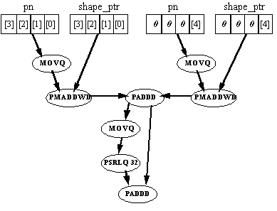
Eight instructions are required to perform one vector-dot product calculation. This option is inefficient for two reasons:
In addition to the fact that this approach is not efficient for the vector dot-product calculation, it does not seem efficient for several other operations in the algorithm which are not inherently parallel.
This alternative operates on two shape vectors simultaneously, effectively unrolling the inner loop once. There is parallelism both within and between calculations since each pmaddwd instruction performs two multiplications for each of the shape vectors. This approach requires rearranging the shape vector codebook array data, since this array contains only constant values, the rearrangement can be done ahead of time without effecting performance. This type of data rearrangement is typical of efficient MMX technology optimized versions. The new memory order is shown in Figure 2.
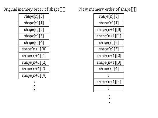
The memory space requirement of this array is 20% higher than the scalar fixed-point version but 40% less than that of the floating-point version.
In addition, the input array needs to be rearranged in a similar manner. This can be done quickly with the MMX technology unpack instructions, and is done outside the loop, so the impact on performance is insignificant.
The data flow diagram for the vector dot-product operation in this alternative is shown in Figure 3.
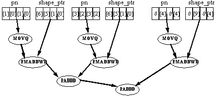
Two vector dot-product operations are performed with eight instructions, which is twice as efficient as the previous approach. Also, other sections of the algorithm which are not inherently parallel can be sped up by performing them for two iterations in parallel. Therefore this approach is selected.
Alternative II, which processes two vectors in parallel, is selected. The loop is unrolled once more, so that two MMX instruction streams can be intermixed, facilitating efficient instruction scheduling (see Section 2.2.4.2). Since each MMX instruction stream operates on two shape vectors, calculations are performed for four shape vectors in each iteration of the loop.
The block diagram in Figure 4 shows one MMX instruction stream processing two shape vectors. The six steps of the inner loop are shown. For each step the number of instructions (within square brackets) and their types is listed. (j refers to the number of the current iteration, cgm0-2 are the cb_gain_mid_X constants.)
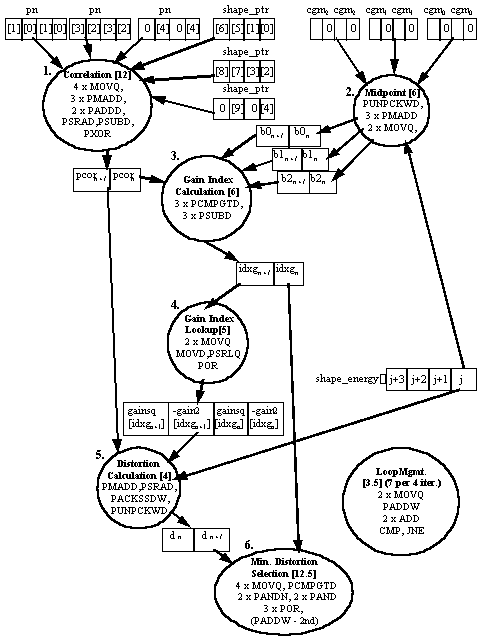
A fractional number of instructions is attributed to the Loop Management and Minimum Distortion Selection sections. This is because they include instructions which only appear in one of the two MMX instruction streams.
This section contains detailed instruction flow diagrams for each of the six steps (Correlation, Midpoint, Gain Index Calculation, Gain Index, Distortion, and Minimum Distortion Selection) of the inner loop. Remember that two shape vectors are being processed in parallel in each instruction stream. In addition, two streams are being executed in each iteration of the new inner loop, and some instructions differ between the two streams (these are noted wherever they appear).
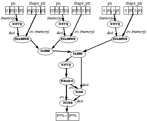
The correlation calculation includes two parts: a vector dot-product calculation and an absolute-value calculation.
This absolute-value calculation is performed by a conditional two's-complement operation. The value is copied and shifted arithmetically 31 bits to the left. This creates two doublewords, each of which is 0 if the original doubleword was positive and 0xffffffff (-1) if the original doubleword was negative. The result of this shift is then used to XOR the original value (thus conditionally inverting the bits) and is subtracted from the original value (thus conditionally adding 1). This amounts to conditionally performing a two's complement operation on each doubleword, depending on if it was originally negative - which is the definition of an absolute value calculation.
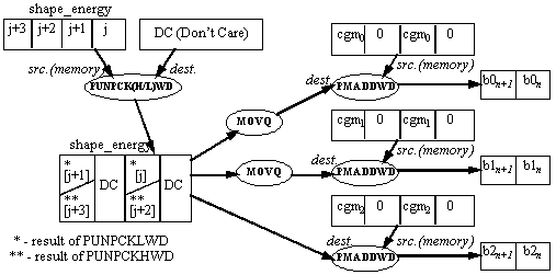
In this section of the inner loop the current shape_energy is multiplied by three constants, generating three bin midpoints which are used in the gain index calculation section. Each instruction stream in the MMX code inner loop performs this calculation for two shape_energy values. Taking j as the index to the four elements being processed by the current loop iteration, one instruction stream performs the midpoint calculation on shape_energy[j] and shape_energy[j+1]; the second instruction stream performs this calculation on shape_energy[j+2] and shape_energy[j+3].
Since it is necessary for the results of the multiplication to be in packed doubleword format, it is convenient to use the PMADDWD instruction rather than the PMULLW or PMULHW instructions. The PMADDWD instruction performs four multiplications and two additions. If only two multiplications are needed, the inputs must be padded (at least one of them with zeros).
An unpack operation is performed between the current four elements of shape_energy and a register (the contents of the register are irrelevant). The instruction used is PUNPCKLWD in the first instruction stream, and PUNPCKHWD in the second. The result is a packed word register which contains the appropriate values of shape_energy in its second and fourth word. This result is copied twice, and the three copies are multiplied with the cb_gain_mid_X constants using the PMADDWD instruction. Note that the constants are stored in memory already padded with zeros.
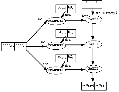
In this section of the inner loop PCOR is compared to three bin midpoints, and the gain index is calculated according to the result. (see Pseudocode sequence in Figure 2). Since cannot be made parallel and are slow as well, they are avoided. The 'all 1s' mask generated by a 'true' result in the packed compare instructions is equal to -1 if interpreted as a signed number. Three masks are generated by comparing pcor to the three midpoints using the PCMPGTD instruction. These masks are added to a constant value of 3, to generate a number between 3 and 0 which is the desired gain index. Note that two gain index values are generated in parallel.
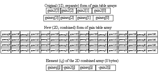
In this section the gain index is used to perform lookups into two tables: gainsq (the gain values squared) and gain2 (the gain values multiplied by two). A table lookup is an operation which is cannot ordinarily be made parallel using MMX technology, but in this case parallelism is achieved nevertheless. This is possible because the tables are very small - four 16-bit entries each. By creating a two-dimensional array, including all possible combinations of two entries from the gain table, two parallel lookups are possible. If both gain tables are combined into one array, then one lookup yields eight bytes which contain two gain2 and two gainsq values (the gain2 values are stored in negative form, since they are used for subtraction in the Distortion Calculation section). If the tables were much larger this would not be feasible due to the extra memory space requirements and resulting cache problems. The structure of the gain table arrays is in Figure 8, and the instruction flow of the lookup is in Figure 9.
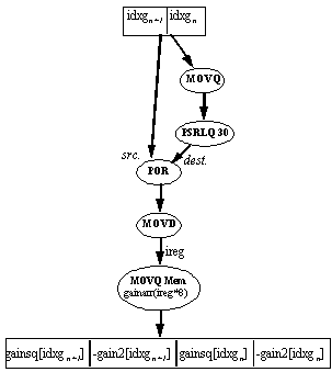
The index (4 bits) into the 2D gain table is the concatenation of two 2-bit indexes, each of which is in a separate doubleword (the output of the gain index calculation). To combine them, the gain index register is copied, shifted and ORed. The combined index is moved to an integer register, which is used to access the correct (8 byte) element in the array.
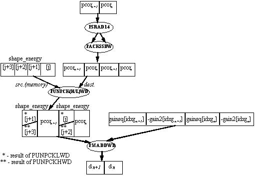
In this section the distortion is calculated. Before the actual distortion calculation, pcor must be shifted 14 bits to the right and clipped (with saturation) to 16 bits (see Example 2.). This is accomplished by one packed shift and one pack instruction (it is packed with itself).
The distortion measure d is calculated by the formula:
This involves two multiplications and a subtraction. If gain2 is stored in negative form, this is two multiplications and an addition, where the inputs have 16-bit precision and the output has 32-bit precision. This is exactly what the PMADDWD instruction does - twice. So one PMADDWD instruction can calculate the distortion for two shape vectors in parallel, if the inputs are formatted correctly. This formatting is performed by one unpack instruction, which interleaves the pcor values with the appropriate shape_energy values. The instruction used is PUNPCKLWD in the first instruction stream, and PUNPCKHWD in the second.
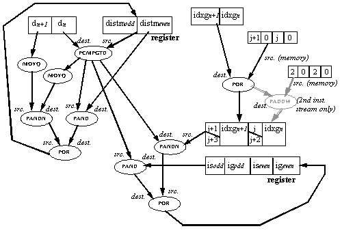
In this section the current d is compared to distm (the minimum distortion so far). If d is smaller, then the current codebook shape and gain vectors fit the input vector better then the best fit so far. In this case the best fit is replaced by the current codebook vector, resulting in the following:
Such a minimum selection operation is inherently serial: the current distm must be found before it can be compared with the next d to find the next distm. However, parallelism can be achieved by using the following method:
Each MMX instruction stream processes two codebook vectors (n and n+1). Packed compare instructions are used for two conditional selection operations in parallel. The best fit found is stored separately for even and odd shape codebook indexes: there is a separate is, ig and distm for odd and even indexes. These are kept separately throughout the inner loop. Only after the inner loop has completed are the two partial minimum values compared to find the actual minimum. Note that the minimum distortion selection of the second instruction stream is dependent on that of the first, so they must be executed in order; this is the only point of dependency between the two instruction streams, which otherwise can be freely intermixed.
The d(n,n+1) and distm(odd,even) values are compared using the PCMPGTD instruction, generating a mask which is used to conditionally select the new distm(odd,even), ig(n,n+1) and is(n,n+1) values. The conditional select operation is done by performing AND and ANDNOT operations with the mask on the new and old values. j/j+1, is(n,n+1) and ig(n,n+1) are in a format which enables doing the conditional select operation for is and ig together. j/j+1 is incremented by 2 for the second instruction stream only (instructions in grey), to become j+2/j+3.
The values is, ig, and distm are kept in 2 registers which are dedicated to holding these values throughout the minimum distortion selection code of both MMX instruction streams. They are loaded from memory before the minimum distortion selection of the first instruction stream and stored after the second. This adds 4 MOVQ instructions per two instruction streams, or an average of 2 MOVQ instructions for each instruction stream.
This section describes various performance optimizations which are used in the code.
Throughout the code, an effort was made (by selection of the operand order) to minimize the number of extra movq instructions needed to copy data. In addition, an attempt was made to minimize the number of instructions with memory operands, since these limit the scheduling opportunities.
Instruction length is also worth noting. Instructions with a length exceeding seven bytes were avoided inside the inner loop. The reason for this is that these instructions can reduce pairing, especially if the pairing is otherwise good (as in this code). Note that since MMX instructions have a two-byte opcode, any MMX instruction using a base or index register and a 32-bit displacement or immediate will exceed seven bytes. This is the reason for the use of EDX to store the address of the gain array; to avoid using base + displacement addressing.
Five out of six sections of the inner loop use four MMX registers or less. This enables the use of two separate sets of MMX registers for the two instruction streams, and freely intermixing instructions (from these five sections) between the streams. In addition, instructions from different sections are also intermixed to enable maximum pairing opportunities. MMX register usage in these sections is as follows:
The minimum distortion selection sections of the two instruction streams have an interdependency, so the instructions of these sections cannot be freely intermixed. MMX register usage in the minimum distortion selection code is as follows:
There is some intermixing of instructions between the minimum distortion selection and other sections of code, especially at the beginning and end. In addition, values are preloaded into registers for the correlation calculation of the next iteration (software pipelining).
The result of these techniques is that the code of the inner loop runs with almost perfect pairing (4 unpaired instructions out of 98) and no stalls. The fact that the instruction order is drastically different than the algorithmic order can reduce readability, which is why the code is extensively commented.
The shape and gain codebooks, the energy array and the temps structure (containing the local variables) should be aligned to 8 bytes to avoid costly misalignment penalties. It is less important that the input array be aligned, since it is copied into aligned locations before the start of the inner loop.
The reason that the local variables are passed as a structure and not held on the stack (see code listing) is that they must be aligned to eight bytes to avoid loss of performance. To pass a structure (the caller must ensure alignment) is one solution, another is to add code to the function prologue and epilogue to align the stack itself to eight bytes (see the MMX™ Technology Developer's Manual).
An optimized floating-point version of this routine executes in 4800 clocks. The MMX technology version executes in about 1750 clocks, which is a performance gain of 2.7X. The performance gain is mostly attributable to the MMX instructions which perform operations on multiple data elements and can be paired, unlike the floating-point instructions. These numbers assume that the data is in the L1 cache . This assumption is true when the codebook search is running as part of a G.728 encoder.
This routine is called 1600 times per second when the G.728 encoder is run in real-time. Therefore the 4800 clock floating-point version consumes 5% of the total CPU power of a 150 MHz Pentium processor, while the MMX technology optimized version which takes 1730 clocks reduces this to 2%.
;ProcedureName: mmx_cb_index;
;Description:
; G.728 codebook search: this is an MMX code implementation of modules 17 and
; 18 of the ITU-T (fromerly CCITT) G.728 recommendation.
; Two iterations of the inner loop have been made parallel, and two of
; these have been unrolled and pipelined for a total of four iterations.
;
;C Prototype
;int mmx_cb_index(
; const short *mmx_cd_shape,
; const short *mmx_energy_result,
; const short *pn,
; short temps[6*4);
;
;NOTE:
; This is a fixed-point version of the algorithm. In comments, the format
; of various variables/tables/constants will be described as xQy where
; x is the number of bits (16 or 32) and y is the number of bits to the
; right of the implicit radix point. (Example: 16Q5). Where there is an
; MMX code-type variable which includes 4 16-bit or 2 32-bit values, the format
; will be described as: 2x32Q5, or 4x16Q7, etc.
;NOTE:
; 'DC' in comments refers to 'Don't Care' values.
;
;Internal Register Usage:
; IA: (Note that it is assumed that the calling program does not need
; eax,ecx, or edx to be preserved - this is true for C programs compiled
; with Microsoft Visual C++, for example).
; eax - general use, and return value
; ebx - pointer into int16_shape_energy: equal to int16_shape_energy + j*8
; it is also used for checking loop termination.
; ecx - pointer (s_p) into shape codebook array (mmx_cb_shape)
; edx - pointer to start of gain array (gainarr) (this is to use base+index
; addressing when accessing this array instead of displacement+index.
; This reduces the size below 8 bytes, and so facilitates pairing).
; edi - pointer to temporary data of 6 quadwords: pn01, pn23, pn4z, distm,
; ig_is, and j_jp1
; esi - pointer to to end of shape energy for loop termination
; MMx:
;
;Inputs: Uses C language stack frame
; Globals:
;
; Input Parameters:
; mmx_cb_shape:PTR WORD - ptr to start of codebook.
; NOTE: The elements in the codebook have been rearranged to facilitate
; speeding up the algorithm. When comments refer to non-consecutive
; indices in the shape array for example s_p[0,1,5,6], this refers
; to the elements in the original, non-rearranged codebook: in
; memory, these elements actually appear in this order.
;
; int16_shape_energy: PTR WORD - ptr to start of energy array.
; pn:PTR WORD - ptr to start input vector (5 x 16bit vector)
; temps: pointer to 6 aligned qwords used for:
; pn01: QWORD - duplicated and aligned copy of pn[0] and pn[1]
; pn23: QWORD - duplicated and aligned copy of pn[2] and pn[3]
; pn4z: QWORD - duplicated and aligned copy of pn[4] (padded with 0s)
; distm: QWORD - distm(even),distm(odd) (2x32Q16) (init to max 32bit)
; ig_is QWORD - ig(even),is(even),ig(odd),is(odd) (4x16)
; j_jp1 QWORD - 0, j, 0, j+1 (4x16) (initialised to 0,-2,0,-1)
;
;Locals: (in the data segment, not the stack)
; Constants:
; cgm0: 4 x SWORD - cb_gain_mid_0, duplicated and padded (w. zeros)
; cgm1: 4 x SWORD - cb_gain_mid_1, duplicated and padded (w. zeros)
; cgm2: 4 x SWORD - cb_gain_mid_2, duplicated and padded (w. zeros)
; gainarr:64 x SWORD - combination and squaring of gain2 & gainsq arrays
; val01: 4 x WORD - 0,-4,0,-3 (for initialising j/j+1)
; inc04 4 x WORD - 0,4,0,4 (for incrementing j/j+1)
; inc02: 4 x WORD - 0,2,0,2 (for converting j/j+1 into j+2/j+3)
; val33: 2 x DWORD - 3,3
; max32: 2 x SDWORD - maximum signed 32-bit value, twice (init. for distm)
; val12_0:4 x SWORD - 12,0,0,0
; val32: QWORD - 32
; masklow:4 x WORD - 0FFFFh, 0, 0FFFFh, 0 (mask out high word in each dword)
;
;Return Value:
; 16-bit integer, in eax - the concatenated gain and codebook indexes for
; the best fit.
;****************************************************************************
INCLUDE iammx.inc ;IA-MMx emulator macros
.486P
.model FLAT
_DATA SEGMENT PARA PUBLIC USE32 'DATA'
pn01 equ [edi] ;pn[0],pn[1],pn[0],pn[1]
pn23 equ [edi+8] ;pn[2],pn[3],pn[2],pn[3]
pn4z equ [edi+16] ;pn[4],0,pn[4],0
distm equ [edi+24] ;distm(even,odd)
ig_is equ [edi+32] ;ig,is(even,odd)
j_jp1 equ [edi+40] ;0,j,0,j+1
cgm0 SWORD 0,5808,0,5808 ;cb_gain_mid_0 (twice, padded)
cgm1 SWORD 0,10164,0,10164 ;cb_gain_mid_1 (twice, padded)
cgm2 SWORD 0,17787,0,17787 ;cb_gain_mid_2 (twice, padded)
gainarr SWORD -4224,545,-4224,545,
-7392,1668,-4224,545,
-12936,5107,-4224,545,
-22638,15640,-4224,545,
-4224,545,-7392,1668,
-7392,1668,-7392,1668,
-12936,5107,-7392,1668,
-22638,15640,-7392,1668
SWORD -4224,545,-12936,5107,
-7392,1668,-12936,5107,
-12936,5107,-12936,5107,
-22638,15640,-12936,5107,
-4224,545,-22638,15640,
-7392,1668,-22638,15640,
-12936,5107,-22638,15640,
-22638,15640,-22638,15640
val01 SWORD 0,-4,0,-3
inc04 SWORD 0,4,0,4
inc02 SWORD 0,2,0,2
val33 DWORD 3,3
max32 SDWORD 7FFFFFFFh,7FFFFFFFh ;maximum 32-bit signed value x 2
val12_0 SWORD 12,0,0,0
val32 QWORD 32
masklow WORD 0FFFFh,0,0FFFFh,0 ;mask out high word in each dword
_DATA ENDS
_TEXT SEGMENT PARA PUBLIC USE32 'CODE'
mmx_cb_index PROC NEAR C PUBLIC USES EBX EDI ESI,
mmx_cb_shape:PTR WORD, int16_shape_energy: PTR WORD, pn: DWORD, temps: PTR WORD
;Initialisation
;--------------
;initialise pointer into mmx_cb_shape (to last 4 vectors in array)
;it will be incremented by 48 at the end of every 4 iterations.
mov ecx, mmx_cb_shape
;initialise pointer into int16_shape_energy: it is equal to
;int16_shape_energy + j*8. t is also used for checking loop termination.
mov ebx, int16_shape_energy
;initialise pointer to start of gain array (gainarr) (this is to use
;base+index addressing when accessing this array instead of
;displacement+index. this reduces the size below 8 bytes, and so
;facilitates pairing).
mov edx, OFFSET gainarr
;initialize pointer to start of temporary data provided by caller
mov edi, temps
;initialize pointer to end of int16_shape_energy, for loop termination.
lea esi, [ebx + 256]
;initialise distm(even,odd) to maximum integer values
movq mm5, max32
movq DWORD PTR distm, mm5
;initialise j/j+1 to 0,-4,0,-3
movq mm7, DWORD PTR val01
movq DWORD PTR j_jp1, mm7
;initialise pn01 with pn[0],pn[1],pn[0],pn[1]
;also load mm3, mm7 registers to prepare for start of loop
mov eax, pn
movq mm3, [eax] ;mm3 contains pn[0-3]
movq mm2, mm3
punpckldq mm3, mm3 ;mm3 contains pn[0],pn[1],pn[0],pn[1]
movq DWORD PTR pn01, mm3 ;move to pn01
movq mm7, mm3 ;now both mm3, mm7 are initialized
;initialise pn23 with pn[2],pn[3],pn[2],pn[3]
;also load mm2, mm6 registers to prepare for start of loop
punpckhdq mm2, mm2 ;mm2 contains pn[2],pn[3],pn[2],pn[3]
movq DWORD PTR pn23, mm2 ;move to pn23
movq mm6, mm2 ;now both mm2, mm6 are initialized
;initialise pn4z with pn[4],0,pn[4],0
;also load mm1, mm5 registers to prepare for start of loop
movq mm1, 8[eax] ;mm1 contains pn[4],0,DC,DC
punpckldq mm1, mm1 ;mm1 contains pn[4],0,pn[4],0
movq DWORD PTR pn4z, mm1 ;move to pn4z
movq mm5, mm1 ;now both mm1, mm5 are initialized
nop ;This nop is to avoid a MASM bug
;Align start of loop to 16 bytes
align 16
nop ;This nop is to avoid a MASM bug
START_LOOP:
;NOTE: comments show for each instruction: to which part of the
;algorithm it belongs, and to which pair of iterations - (j,j+1) or
;(j+2,j+3). This is to facilitate readability after software pipelining
;is performed (which will mix instructions from different sections
;and iterations)
;NOTE: here spacing between instructions indicates expected pairing on Pentium Pro.
;Start of loop
;-------------
;In this section 5 sections of both iteration pairs (j,j+1) and
;(j+2,j+3) are made parallel. The sections are:
;1. correlation (corr) - do VDP between pn and shape_ptr (s_p), abs.
; Note that out of the instruction which load pn[] into registers,
; some appear here and some appear at the end of the loop (and before
; the start of the loop).
; NOTE - in this section comments such as s_p[0,1,5,6] refer to the
; order of the elements in the original, non-rearranged codebook:
; the array which is accessed by s_p is arranged so that these
; elements appear in this order in memory.
;2. midpoint calculation (mid) - unpack low 2 elements (out of
; current 4) of int16_shape_energy with an (uninitialised) register,
; then multiply w. cgm0,1,2 to produce b0,1,2.
;3. gain index calculation (gidx) - compare pcor(j,j+1)/(j+2,j+3)
; to bX(j,j+1)/(j+2,j+3) then add results (-1 if bX > pcor, 0 else)
; to 3.
;4. gain index lookup (glook) - copy/shift logic right(by 30) & OR
; idxg w. itself to combine (j,j+1)/(j+2,j+3) indices into one index,
; then do lookup w. this combined index into a combined -gain2,
; gainsq table.
;5. distortion calculation (dcalc)- shift pcor right by 14, and pack it
; w. itself (thus saturating it to 16 bits and copying it). Then do
; unpack low with shape_energy, and pmadd w. gain vector (mm2)
; (d=int16_shape_energy*gainsq - pcor*gain2)
; Every line of code is commented as to which section and iteration
; pair it belongs to.
;Note also that instructions related to loop management (loop_mgmt)
;are scattered throughout the code.
;The two iteration pairs can be freely made parallel since (in these
;sections) they use 2 distinct groups of 4 MMX registers each:
;(j,j+1) uses mm0,mm1,mm2,mm3 and (j+2,j+3) uses mm4,mm5,mm6,mm7.
pmaddwd mm3, [ecx] ;corr(j,j+1): pn01*s_p[0,1,5,6]
movq mm6, mm2 ;corr(j+2,j+3): load pn23 into reg.
pmaddwd mm2, 8[ecx] ;corr(j,j+1): pn23*s_p[2,3,7,8]
movq mm5, mm1 ;corr(j+2,j+3): load pn4z into reg.
pmaddwd mm7, 24[ecx] ;corr(j+2,j+3): pn01*s_p[12,13,17,18]
pmaddwd mm6, 32[ecx] ;corr(j+2,j+3): pn23*s_p[14,15,19,20]
pmaddwd mm1, 16[ecx] ;corr(j,j+1): pn4z*s_p[9],0,[9],0
paddd mm2, mm3 ;corr(j,j+1): 1st accumulate
pmaddwd mm5, 40[ecx] ;corr(j+2,j+3): pn4z*s_p[21],0,[21],0
movq mm0, DWORD PTR j_jp1 ;loop_mgmt: load j_jp1 for incrementing
paddd mm6, mm7 ;corr(j+2,j+3): 1st accumulate
paddw mm0, DWORD PTR inc04 ;loop_mgmt: inc. j/j+1 by 0,4,0,4
paddd mm1, mm2 ;corr(j,j+1): 2nd acc, VDP in mm1
movq mm3, mm1 ;corr(j,j+1): start abs (copy)
paddd mm5, mm6 ;corr(j+2,j+3): 2nd acc, VDP in mm5
movq DWORD PTR j_jp1, mm0 ;loop_mgmt: store incremented j/j+1
psrad mm3, 31 ;corr(j,j+1): shift the copy
punpcklwd mm0, [ebx] ;mid(j,j+1): s_e[j],[j+1]
pxor mm1, mm3 ;corr(j,j+1): xor w. shifted
movq mm2, mm0 ;mid(j,j+1): copy
movq mm7, mm5 ;corr(j+2,j+3): start abs (copy)
pmaddwd mm2, DWORD PTR cgm1 ;mid(j,j+1): b1(j,j+1) in mm2
psubd mm1, mm3 ;corr(j,j+1): sub, abs in mm1
;here the correlation result pcor(j,j+1) is in mm1
punpckhwd mm4, [ebx] ;mid(j+2,j+3): s_e[j+2],[j+3]
movq mm3, mm0 ;mid(j,j+1): copy
pmaddwd mm3, DWORD PTR cgm0 ;mid(j,j+1): b0(j,j+1) in mm3
psrad mm7, 31 ;corr(j+2,j+3): shift the copy
pmaddwd mm0, DWORD PTR cgm2 ;mid(j,j+1): b2(j,j+1) in mm0
pxor mm5, mm7 ;corr(j+2,j+3): xor w. shifted
psubd mm5, mm7 ;corr(j+2,j+3): sub, abs in mm5
;here the correlation result pcor(j+2,j+3) is in mm5
movq mm7, mm4 ;mid(j+2,j+3): copy
pmaddwd mm7, DWORD PTR cgm0 ;mid(j+2,j+3): b0(j+2,j+3) in mm7
pcmpgtd mm2, mm1 ;gidx(j,j+1): compare pcor to b1
movq mm6, mm4 ;mid(j+2,j+3): copy
pcmpgtd mm3, mm1 ;gidx(j,j+1): compare pcor to b0
paddd mm3, val33 ;gidx(j,j+1): add b0 cmp results
pcmpgtd mm0, mm1 ;gidx(j,j+1): compare pcor to b2
pmaddwd mm6, DWORD PTR cgm1 ;mid(j+2,j+3): b1(j+2,j+3) in mm6
paddd mm2, mm3 ;gidx(j,j+1): add b1 cmp results
pmaddwd mm4, DWORD PTR cgm2 ;mid(j+2,j+3): b1(j+2,j+3) in mm4
paddd mm0, mm2 ;gidx(j,j+1): add b2 cmp results
;here idxg(j,j+1) is in mm0.
pcmpgtd mm7, mm5 ;gidx(j+2,j+3): compare pcor to b0
movq mm2, mm0 ;glook(j,j+1): copy idxg
pcmpgtd mm6, mm5 ;gidx(j+2,j+3): compare pcor to b1
psrlq mm2, 30 ;glook(j,j+1): shift copy right
pcmpgtd mm4, mm5 ;gidx(j+2,j+3): compare pcor to b2
por mm2, mm0 ;glook(j,j+1): or idxg w. copy
paddd mm7, val33 ;gidx(j+2,j+3): add b0 cmp results
psrad mm1, 14 ;dcalc(j,j+1): pcor>>= 14: pcor>>= 14
movd eax, mm2 ;glook(j,j+1): mov to index reg.
packssdw mm1, mm1 ;dcalc(j,j+1): pack pcor, sat to 16
;here mm1 contains pcor(j),pcor(j+1),pcor(j),pcor(j+1)
punpcklwd mm1, [ebx] ;dcalc(j,j+1):pcor,s_e[j,j+1]
;here mm1 contains:
;pcor(j),int16_shape_energy[j],pcor(j+1),int16_shape_energy[j+1]
paddd mm6, mm7 ;gidx(j+2,j+3): add b1 cmp results
movq mm2, DWORD PTR [edx+eax*8];glook(j,j+1): lookup w. index
;here mm2 contains:
;-gain2[idxg(j)],gainsq[idxg(j)],-gain2[idxg(j+1)],gainsq[idxg(j+1)]
paddd mm4, mm6 ;gidx(j+2,j+3): add b2 cmp results
;here idxg(j+2,j+3) is in mm4.
pmaddwd mm1, mm2 ;dcalc(j,j+1): calc d(j,j+1)
;here mm1 contains d(j),d(j+1)
movq mm6, mm4 ;glook(j+2,j+3): copy idxg
;Here the 5 sections of the iteration pair (j,j+1) have completed
;execution. We parallelise the remaining sections (dcalc and part of
;glook) of (j+2,j+3) with the start of the 'mind' module of (j,j+1).
;minimum distortion selection (mind): do conditional mov's between
;new and old dist, ig/is.
;distm(even,odd) is compared w. d(j,j+1)and distm and ig/is are
;updated accordingly.
por mm0, DWORD PTR j_jp1 ;mind(j,j+1): OR j/j+1 w. idxg
;here mm0 contains idxg(j),j,idxg(j+1),j+1]
psrlq mm6, 30 ;glook(j+2,j+3): shift copy right
por mm6, mm4 ;glook(j+2,j+3): or idxg w. copy
psrad mm5, 14 ;dcalc(j+2,j+3): pcor>>= 14:
movq mm3, DWORD PTR distm ;mind(j,j+1): load mm3 w. distm
movq mm2, mm1 ;mind(j,j+1): copy d
movd eax, mm6 ;glook(j+2,j+3): mov to index reg.
packssdw mm5, mm5 ;dcalc(j+2,j+3): pack pcor, sat to 16
;here mm5 contains pcor(j+2),pcor(j+3),pcor(j+2),pcor(j+3)
punpckhwd mm5, [ebx] ;dcalc(j+2,j+3):w. s_e[j+2,j+3]
;here mm5 contains:
;pcor(j+2),int16_shape_energy[j+2],pcor(j+3),int16_shape_energy[j+3]
pcmpgtd mm1, mm3 ;mind(j,j+1): cmp distm to d
;here mm1 contains a mask (1's = d>distm) (2x32)
movq mm6, DWORD PTR [edx+eax*8];glook(j+2,j+3): lookup w. index
;here mm6 contains:
;-gain2[idxg(j+2)],gainsq[idxg(j+2)],-gain2[idxg(j+3)],gainsq[idxg(j+3)]
pand mm3, mm1 ;mind(j,j+1): AND distm w. mask
pmaddwd mm5, mm6 ;dcalc(j+2,j+3): calc d(j+2,j+3)
;here mm5 contains d(j+2),d(j+3)
movq mm6, mm1 ;mind(j,j+1)
;In this section we just have mind(j,j+1,(j+2,j+3) made parallel with
;some loop management(loop_mgmt) and some instructions from correlation
;calculation (corr).
movq mm7, DWORD PTR ig_is ;mind(j,j+1): load mm7 w. ig_is
pandn mm6, mm2 ;mind(j,j+1): AND d w. reverse mask
por mm3, mm6 ;mind(j,j+1): OR masked d, distm
;conditional move on distm done - now do cond. move on is, ig
pand mm7, mm1 ;mind(j,j+1): AND ig,is w. mask
por mm4, DWORD PTR j_jp1 ;mind(j+2,j+3): OR j/j+1 w. idxg
pandn mm1, mm0 ;mind(j,j+1): AND idxg,j w. inv mask
paddd mm4, DWORD PTR inc02 ;add 0,2,0,2 to make j+2/j+3
;here mm4 contains idxg(j+2),j+2,idxg(j+3),j+3]
por mm7, mm1 ;mind(j,j+1): OR masked idxg/j, ig/is
movq mm2, mm5 ;mind(j+2,j+3): copy d
pcmpgtd mm5, mm3 ;mind(j+2,j+3): cmp distm to d
;here mm5 contains a mask (1's = d>distm) (2x32)
movq mm6, mm5 ;mind(j+2,j+3)
pand mm3, mm5 ;mind(j+2,j+3): AND distm w. mask
pandn mm6, mm2 ;mind(j+2,j+3): AND d w. inv mask
pand mm7, mm5 ;mind(j+2,j+3): AND ig,is w. mask
movq mm2, DWORD PTR pn23 ;corr(j,j+1): load pn23 into reg.
pandn mm5, mm4 ;mind(j+2,j+3): idxg,j AND inv mask
movq mm1, DWORD PTR pn4z ;corr(j,j+1): load pn4z into reg.
por mm3, mm6 ;mind(j+2,j+3): OR masked d, distm
add ecx, 48 ;loop_mgmt: increment s_p by 48
add ebx, 8 ;loop_mgmt: increment pointer by 8
movq DWORD PTR distm, mm3 ;mind(j+2,j+3): store mm3 in distm
por mm7, mm5 ;mind(j+2,j+3): merge idxg/j, ig/is
movq mm3, DWORD PTR pn01 ;corr(j,j+1): load pn01 into reg.
movq DWORD PTR ig_is, mm7 ;mind(j+2,j+3): store mm7 in ig_is
movq mm7, mm3 ;corr(j+2,j+3): load pn01 into reg.
cmp ebx, esi ;loop_mgmt
jb START_LOOP ;loop_mgmt: branch
;After loop - postprocess results
;--------------------------------
;In this section we first find the minimum out of distm(even)/distm(odd), and
;select is and ig accordingly.
;Then pcor is recalculated and 4 added to ig if it is negative.
;format is, ig so that _ig_ is in 3 LSBits, and _is_ is in 7 bits above.
;(currently ig is in bits 0-15. and is in bits 16-31).
movq mm6, DWORD PTR ig_is
movq mm3, mm6
psrld mm6, 13
por mm6, mm3
pand mm6, DWORD PTR masklow
;select is, ig according to minimum distm.
movq mm5, DWORD PTR distm
movd eax, mm5 ;distm(even) -> eax
psrlq mm5, 32
movd ebx, mm5 ;distm(odd) -> ebx
pxor mm7, mm7 ;initialise even/odd indicator
cmp eax, ebx
jle MIN_EVEN ;if distm(even)<=distm(odd), jmp
movq mm7, DWORD PTR val32 ;mm7 is 32 if distm(odd) is min, 0 else
MIN_EVEN:
psrlq mm6, mm7 ;shift ig/is(min) into low 32 bits
movq mm4, mm6 ;ig/is of minimum distm -> mm4
psrld mm6, 4 ;now LSW of mm6 has is/2
pmullw mm6, DWORD PTR val12_0 ;multiplied by 12 for index into codebook
movd esi, mm6
;recalculate VDP
mov ecx, mmx_cb_shape ;point ecx back to begining of codebook
movq mm0, DWORD PTR pn01
movq mm1, DWORD PTR pn23
movq mm2, DWORD PTR pn4z
pmaddwd mm0, [ecx+esi*2]
pmaddwd mm1, [ecx+esi*2+8]
paddd mm1, mm0
pmaddwd mm2, [ecx+esi*2+16]
paddd mm2, mm1
;here recalculated pcor is in mm2 (either the high or low DWord)
psrlq mm2, mm7 ;shift pcor into low 32 bits
;here recalculated pcor is in low DWord of mm2 (high dword may have garbage)
;if result negative, add 4 to ig.
psrld mm2, 31
pslld mm2, 2
por mm4, mm2
movd eax, mm4 ;return value
emms ;clear MM state
ret 0
mmx_cb_index ENDP
_TEXT ENDS
END
@
