![[INTEL NAVIGATION HEADER]](../../PIX/HEADER.GIF)
Intel386(TM) EX Embedded Microprocessor Extended Temperature Addendum to Intel386(TM) EX Embedded Microprocessor (272420-004)
Extended Temperature
Addendum to Intel386 EX Embedded Microprocessor
- Static Intel386(TM) CPU Core
- Low Power Consumption
- Operating Power Supply 2.7V to 5.5V
- Operating Frequency
- 16 MHz at 2.7V to 3.3V;
- 20 MHz at 3.0V to 3.6V;
- 25 MHz at 4.5V to 5.5V
- Transparent Power-management System Architecture
- Intel System Management Mode Architecture Extension for Truly Compatible Systems
- Power Management Transparent to Operating Systems and Applications Programs
- Programmable Power-management Modes
- Powerdown Mode
- Clock Stopping at Any Time
- Only 10-20 mA Typical CPU Sink Current
- Full 32-bit Internal Architecture
- 8-, 16-, 32-bit Data Types
- 8 General Purpose 32-bit Registers
- Runs Intel386 Architecture Software in a Cost-effective 16-bit Hardware Environment
- Runs Same Applications and Operating Systems as the Intel386 SX and Intel386 DX Processors
- Object Code Compatible with 8086, 80186, 80286, and Intel386 Processors
- High-perofrmance 16-bit Data Bus
- Two-clock Bus Cycles
- Address Pipelining Allows Use of Slower Inexpensive Memories
- Integrated Memory Management Unit
- Virtual Memory Support
- Optional On-chip Paging
- 4 Levels of Hardware-enforced Protection
- MMU Fully Compatible with Those of the 80286 and Intel386 DX Processors
- Virtual 8086 Mode Allows Execution of 8086 Software in a Protected and Paged System
- Large Uniform Address Space
- 64 Megabyte Physical
- 64 Terabyte Virtual
- 4 Gigabyte Maximum Segment Size
- Numerics Support with Intel387(TM) SX and Intel387 SL Math Coprocessors
- On-chip Debugging Support Including Breakpoint Registers
- Complete System Development Support
- High Speed CHMOS Technology
- Two Package Types
- 132-pin Plastic Quad Flatpack
- 144-pin Thin Quad Flatpack
- Integrated Peripheral Functions
- Clock and Power Management Unit
- Chip-select Unit
- Interrupt Control Unit
- Timer Control Unit
- Watchdog Timer Unit
- Asynchronous Serial I/O Unit
- Synchronous Serial I/O Unit
- Parallel I/O Unit
- DMA and Bus Arbiter Unit
- Refresh Control Unit
- JTAG-compliant Test-logic Unit
The Intel386 EX Embedded Microprocessor is a highly integrated, 32-bit fully static CPU optimized for embedded control applications. With a 16-bit external data bus, a 26-bit external address bus, and Intel's Systems management Mode (SMM), the Intel386 EX microprocessor brings the vast software library of Intel386 architecture to embedded systems. It provides the performance benefits of 32-bit programming with the cost savings associated with 16-bit hardware systems.
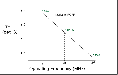
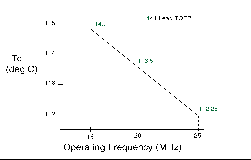
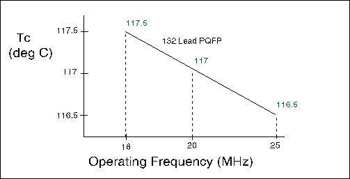
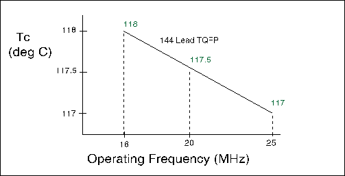
The Extended Temperature version of the Intel386 EX microprocessor is specified for operation with a minimum case temperature (TCASE(min)) of -40°C and a maximum case temperature (TCASE(max)) dependent on power dissipation (see figures 1 through 4). The case temperature can be measured in any environment to determine whether the device is within the specified operating range. The case temperature should be measured at the center of the top surface opposite the pins.
An increase in the ambient temperature (TA) causes a proportional increase in the case temperature (TCASE) and the junction temperature (TJ). A packaged device produces thermal resistance between junction and case temperature (thetaJC) and between junction and ambient temperature (thetaJA). The relationships between the temperature and thermal resistance parameters are expressed by these equations (P = power dissipated as heat = VCC × ICC):
1. TJ = TCASE + P × thetaJC
2. TA = TJ - P × thetaJA
3. TCASE = TA + P × thetaJA - thetaJC
A safe operating temperature can be calculated from the above equations using the maximum TJ of 120°C, the power drawn by the chip in the specific design, and the thetaJC value from Table 1. The thetaJA value depends on the airflow (measured at the top of the chip) provided by the system ventilation, board layout, board thickness, and potentially other factors in the design of the application
Table 1. Thermal Resistance (0°C/W) ja, jc
| Package |
thetaJC |
thetaJA(oC/W) vs. Airflow (ft./min.) |
| |
0 | 100 | 200 |
| 132 PQFP | 6 | 41 | 36 | 32 |
| 144 TQFP | 5 | 36 | 31 | 27 |
Figures 1 through 4 provide maximum case temperature as a function of frequency. The temperature values given in each graph are based on the junction temperature of 120°C.

Figure 1. Maximum Case Temperature vs. Frequency for Typical Power Values (132-lead PQFP, Vcc = 5.5V)

Figure 2. Maximum Case Temperature vs. Frequency for Typical Power Values (144-lead TQFP, Vcc = 5.5V)

Figure 3. Maximum Case Temperature vs. Frequency for Typical Power Values (132-lead PQFP, Vcc = 3.6V)

Figure 4. Maximum Case Temperature vs. Frequency for Typical Power Values (144-lead TQFP, Vcc = 3.6V)
Legal Stuff © 1997 Intel Corporation
